Goodrive30 Series VFD Optional peripheral accessories
-157-
C.2 Power supply
Ensure that the voltage class of the VFD is consistent with that of the
grid.
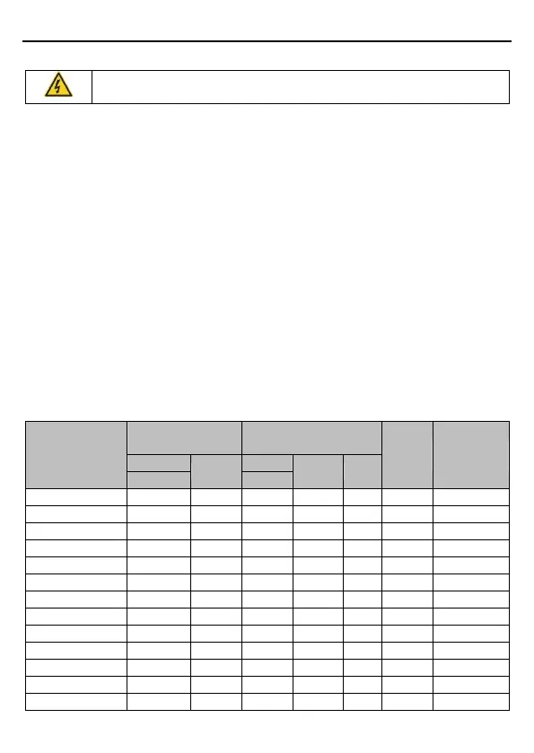
C.3 Cables
C.3.1 Power cables
The sizes of the input power cables and motor cables must meet the local regulation.
Note: If the conductivity of the shielding layer of the motor cables cannot meet the
requirements, separate PE conductors must be used.
C.3.2 Control cables
All analog control cables and cables used for frequency input must be shielded cables.
Relay cables need to be those with metal braided shield layers.
Keypads need to be connected by using network cables. In complicated electromagnetic
environments, shielded network cables are recommended.
Note:
Analog signals and digital signals cannot use the same cables, and their cables must be
arranged separately.
Check the insulation conditions of the input power cable of a VFD according to the local
regulations before connecting it.
Recommended
cable size (mm²)
Connecting cable size
(mm
2
)

 Loading...


