Goodrive30 Series VFD Installation guidelines
-18-
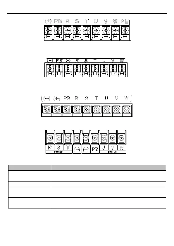
Figure 3-5 Main circuit terminal diagram for VFD models of 3PH 220V, ≤0.75kW and 3PH
380V, ≤2.2kW)
Figure 3-6 Main circuit terminal diagram for VFD models of 3PH 220V, ≥1.5kW and 3PH 380V,
4-22kW)
Figure 3-7 Main circuit terminal diagram for VFD models of 3PH 380V, 30-37kW
Figure 3-8 Main circuit terminal diagram for VFD models of 3PH 380V, 45-110kW)
1PH AC input terminal, connected to the grid.
3PH AC input terminal, connected to the grid.
Connected to external dynamic braking resistor terminal
Input terminal of the braking unit or DC bus
3PH AC output terminal, connected to the motor in most cases.
Grounding terminal for safe protection, and proper grounding is
required for each machine.
Note:
Do not use asymmetrical motor cables. If there is a symmetrical grounding conductor in
the motor cable besides the conductive shielded layer, ground the grounding conductor on
the VFD and motor ends.

 Loading...


