Goodrive30 Series VFD Communication protocol
-126-
In a character frame, only the data bits carry information. The start bit, check bit, and stop bit
are used to facilitate the transmission of the data bits to the destination device. In practical
applications, you must set the data bits, parity check bits, and stop bits consistently.
In RTU mode, a new frame always must be preceded by a time gap with a mini. length of 3.5
bytes. On a network where the transmission rate is calculated based on the baud rate, time
gap of 3.5 bytes can be easily obtained. After the idle time ends, the data domains are sent in
the following sequence: slave address, operation command code, data, and CRC check
character. Each byte sent in each domain includes hexadecimal characters (0–9, A–F). The
network devices always monitor the communication bus. After receiving the first domain
(address information), each network device identifies the byte. After the last byte is sent, a
similar transmission interval (with a mini. length of 3.5 bytes) is used to indicate that the frame
transmission ends. Then, the transmission of a new frame starts.
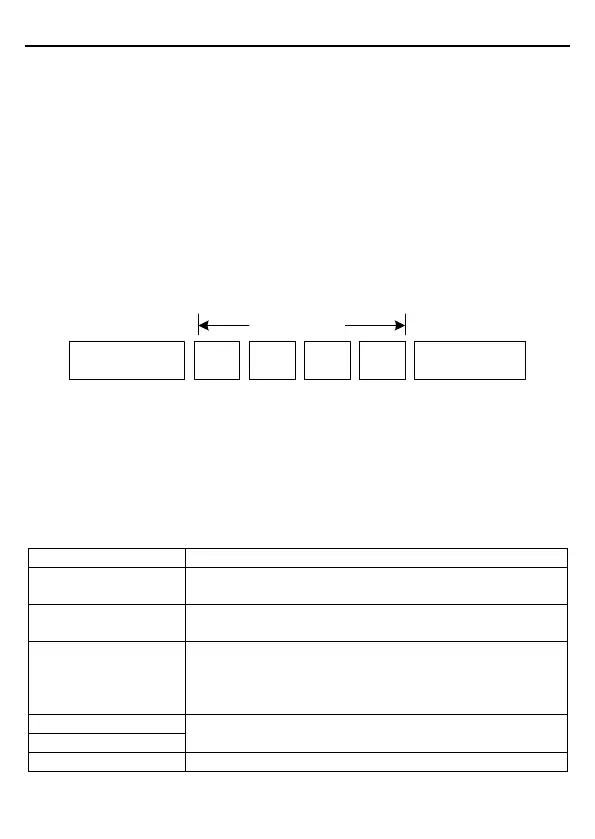
RTU data frame format
Modbus packet
Start with a time gap
(with a min. length of 3.5
bytes)
Slave
address
Function
code
Data Check
End with a time gap
(with a min. length of
3.5 bytes)
The information of a frame must be sent in a continuous data flow. If there is an interval
greater than the transmission time of 1.5 bytes before the transmission of the entire frame is
complete, the receiving device deletes the incomplete information, and mistakes the
subsequent byte for the address domain of a new frame. Similarly, if the transmission interval
between two frames is shorter than the time gap with a min. length of 3.5 bytes, the receiving
device mistakes it for the data of the last frame. The CRC check value is incorrect due to the
disorder of the frames, and thus a communication fault occurs.
The following table describes the standard structure of an RTU frame.
T1-T2-T3-T4 (time gap with a min. length of 3.5 bytes)
ADDR (slave address
domain)
Communication address: 0–247 (in decimal system) (0 indicates
the broadcast address)
03H: read slave parameters
06H: write slave parameters
Data domain
DATA (N-1)
…
DATA (0)
Data of 2*N bytes, main content of the communication as well as
the core of data exchanging
Detection value: CRC (16 bits)
T1-T2-T3-T4 (time gap with a min. length of 3.5 bytes)

 Loading...


