Goodrive30 Series VFD Function parameter list
-61-
5: Multi-step running
6: PID
7: Modbus communication
8–10: Reserved
Note: For setting methods 1–7, 100%
corresponds to the rated motor voltage.
Voltage set
through
keypad
The function code is the voltage digital setting
when "keypad” is selected as the voltage setting
channel.
Setting range: 0.0% –100.0%
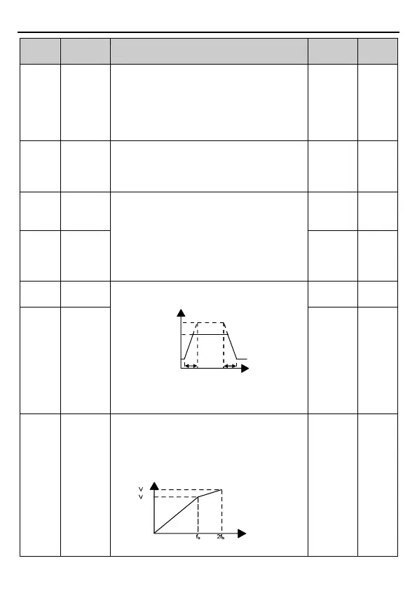
Voltage increase time means the time needed for
the VFD to accelerate from min. output voltage to
the max. output frequency.
Voltage decrease time means the time needed
for the VFD to decelerate from the max. output
frequency to min. output voltage.
Setting range: 0.0–3600.0s
The function codes are used to set the upper and
lower limits of output voltage.
Vmax
Vmin
Vset
t1
t2
Time t
t1=P04.29
t2=P04.30
Setting range of P04.31: P04.32 –100.0% (of the
motor rated voltage)
Setting range of P04.32: 0.0%–P04.31
Weakening
coefficient
in constant
power zone
The function code is used to adjust the output
voltage of the VFD in SVPWM mode during
flux-weakening.
Note: This parameter is invalid in the constant
torque mode.
Output voltage V
Output frequency f
(P04.33-1.00)*Vb
out
b
Setting range of P04.33: 1.00–1.30

 Loading...


