EasyManuals Logo

INVT Goodrive30 VFD Series User Manual

INVT Goodrive30 VFD Series
175 pages
To Next Page IconTo Next Page
To Previous Page IconTo Previous Page
Page #74 background imageLoading...
Page #74 background image
Goodrive30 Series VFD Function parameter list
-68-
Function
code
Name
Description
Default
Modify
P05.28
S8
switch-on
delay
0.000s
P05.29
S8
switch-off
delay
0.000s
P05.30
HDI
switch-on
delay
0.000s
P05.31
HDI
switch-off
delay
0.000s
P05. 32
Lower limit
of AI1
The function code defines the relationship
between the analog input voltage and its
corresponding set value. If the analog input
voltage beyond the set minimum or maximum
input value, the VFD will count at the minimum or
maximum one.
When the analog input is the current input, the
corresponding voltage of 020 mA is 010V.
In different cases, the corresponding rated value
of 100.0% is different. See the application for
detailed information.
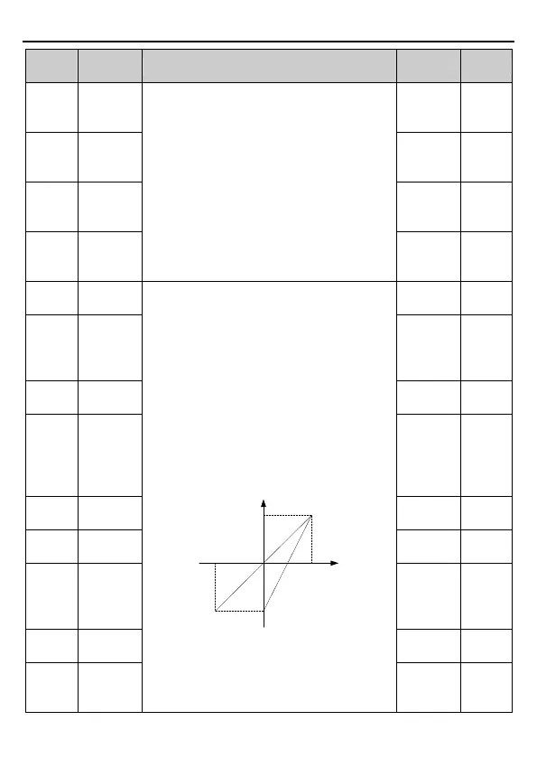
The following figure illustrates different
applications:
-100%
100%
Corresponding setting
AI
-10V
10V
20mA
0
AI3
AI1/AI2
Input filter time: This parameter is used to adjust
the sensitivity of the analog input. Increasing the
value properly can enhance the anti-interference
of the analog, but weaken the sensitivity of the
analog input.
0.00V
P05.33
Correspond
ing setting
of the lower
limit of AI1
0.0%
P05.34
Upper limit
of AI1
10.00V
P05.35
Correspond
ing setting
of
the upper
limit of AI1
100.0%
P05.36
AI1 input
filter time
0.100s
P05.37
Lower limit
of AI2
0.00V
P05.38
Correspond
ing setting
of the lower
limit of AI2
0.0%
P05.39
Upper limit
of AI2
10.00V
P05.40
Correspond
ing setting
of
100.0%

Table of Contents

Questions and Answers:

Question and Answer IconNeed help?

Do you have a question about the INVT Goodrive30 VFD Series and is the answer not in the manual?

INVT Goodrive30 VFD Series Specifications

General IconGeneral
BrandINVT
ModelGoodrive30 VFD Series
CategoryInverter
LanguageEnglish

Related product manuals