Goodrive30 Series VFD Function parameter list
-93-
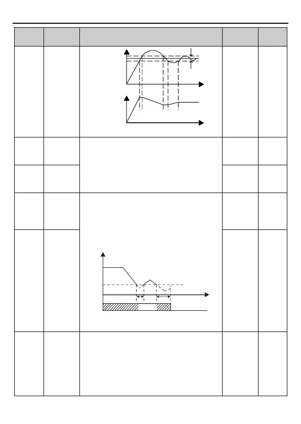
Output frequency f
Time t
Feedback value
Deviation
limit
Reference value
Time t
Setting range: 0.0–100.0%
Upper limit
value of PID
output
The two function codes are used to set the upper
/lower limit value of PID regulator.
100.0% corresponds to max. output frequency
(P00.03) or max. output voltage (P04.31).
Setting range of P09.09: P09.10–100.0%
Setting range of P09.10: -100.0%–P09.09
Lower limit
value of PID
output
Feedback
offline
detection
value
Set the PID feedback offline detection value,
when the detection value is no more than the
feedback offline detection value, and the
duration exceeds the value set in P09.12, the
VFD will report "PID feedback offline fault", and
keypad displays PIDE.
Time t
Output frequency f
t1
t2
P09.11
t1< t2, so the VFD continues running
t2=P09.12
Running Fault output PIDE
PIDE
Setting range of P09.11: 0.0–100.0%
Setting range of P09.12: 0.0–3600.0s
Feedback
offline
detection
time
0x0000–0x1111
Ones place:
0: Continue integral control after the frequency
reaches upper/lower limit. The integration shows
the change between the reference and the
feedback unless it reaches the internal integral
limit. When the trend between the reference and

 Loading...


