Functionality
USER MANUAL FPC 200 - 3/2017 67
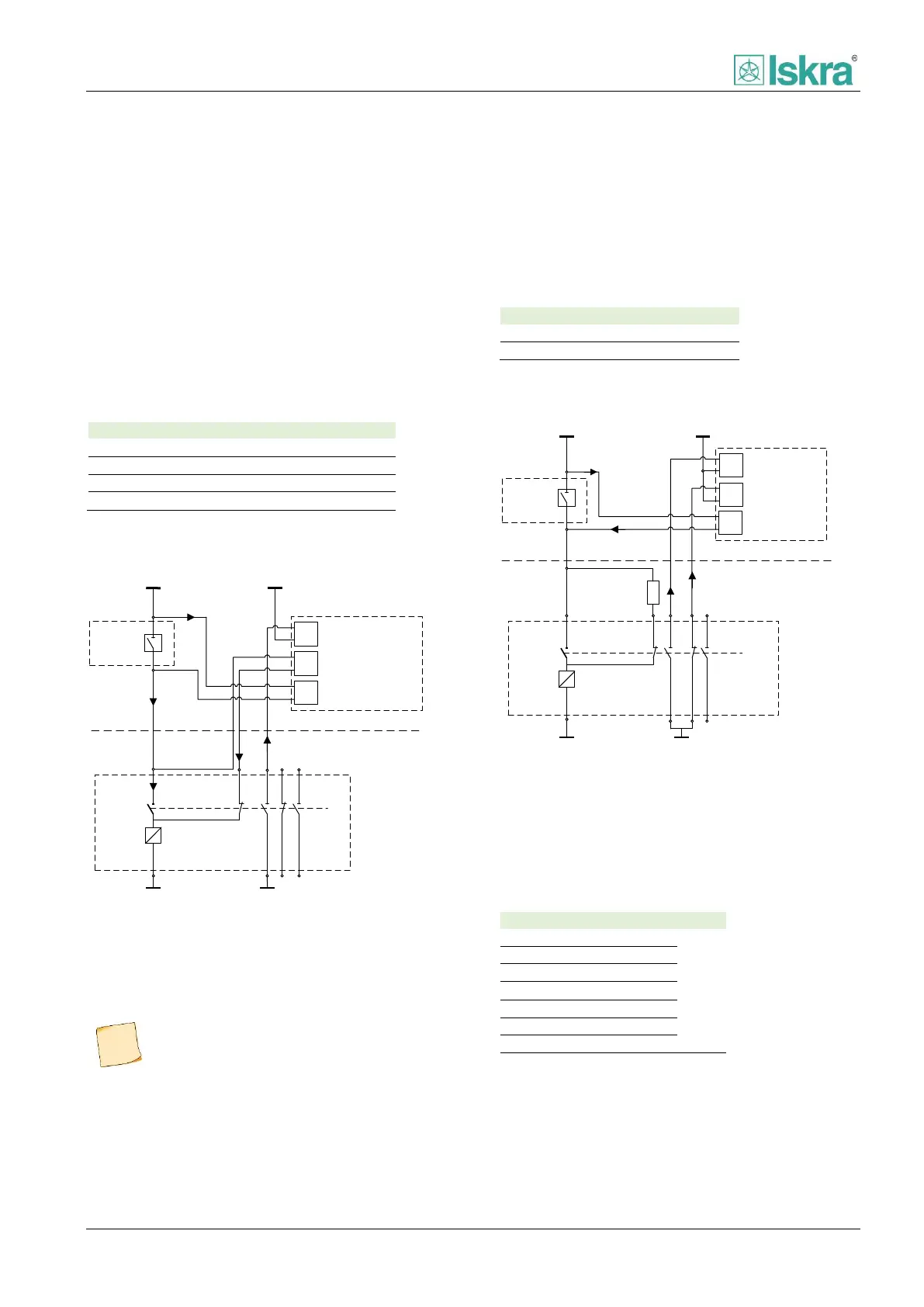
2.6.2.3 Mode 2
In order to supervise section between trip contact
compartment and circuit breaker compartment when
CB is in open position, a control diagram used in Mode 2
[Figure 2.40] can be used by adding two additional wires
to circuit breaker compartment.
It should be noted that by using this scheme, both of
trip circuit supervision digital inputs are connected in
serial. The case occurs when circuit breaker is in open
position and none of trip contacts is active. This
situation will result in a valid position when both of the
contacts are active.
After the Delay00 time elapses.
Table 60: TCS function response according to inputs using
Mode 2 setting.
Trip Coil
DI1
DI2
+
+
-
-
ITCS
ITCS
ITCS
FPC
Circuit
breaker
Trip
contact
CB closed
TCS 1
DI3
+
-
CB open
ITCS2
I52b
Relay compartment
Circuit breaker compartment
L+/L1
L-/N
L+/L1
L-/N
Figure 2.40 Trip circuit supervision with two digital inputs
tailored for full line control of trip circuit in both positions of
circuit breaker. The diagram also implies aditional digital input
to be used as circuit breaker closed position.
Please note that a trip line inside the trip
contact compartment (example can be
seen on Figure 2.40) cannot be supervised
using any of the schemes mentioned in this
section.
2.6.2.4 Mode 3
Mode 3 is a single TCS input mode. The benefit of using
one digital input is that no additional wiring from the
device to the circuit breaker compartment is needed. It
should be noted that by using this scheme an additional
external resistor is needed. By using the resistor a trip
circuit is supervised in closed and opened position of CB.
After the Delay00 time elapses
Table 61: TCS function response according to inputs using
Mode 3 setting.
Trip Coil
DI1
DI2
+
+
-
-
I52a
I52b
FPC
Circuit
breaker
Rext
DI3
+
-
ITCS
ITCS
TCS 1
Trip
contact
CB closed 52a
CB open 52b
Relay compartment
Circuit breaker compartment
L-/N
L+/L1
L+/L1
L-/N
Figure 2.41 Trip circuit supervision using only one digital input
and external resistor. The diagram also implies connection of
circuit breaker status.
2.6.2.4.1 External resistor estimation
Estimated external resistor R
ext
value is determined in
the table below.
Figure 42 External resistor values depending on voltage level.