Engineering manual - UniSAB III 1.10.8
001930 en 2021.06
87/346
Compressor control and surveillance
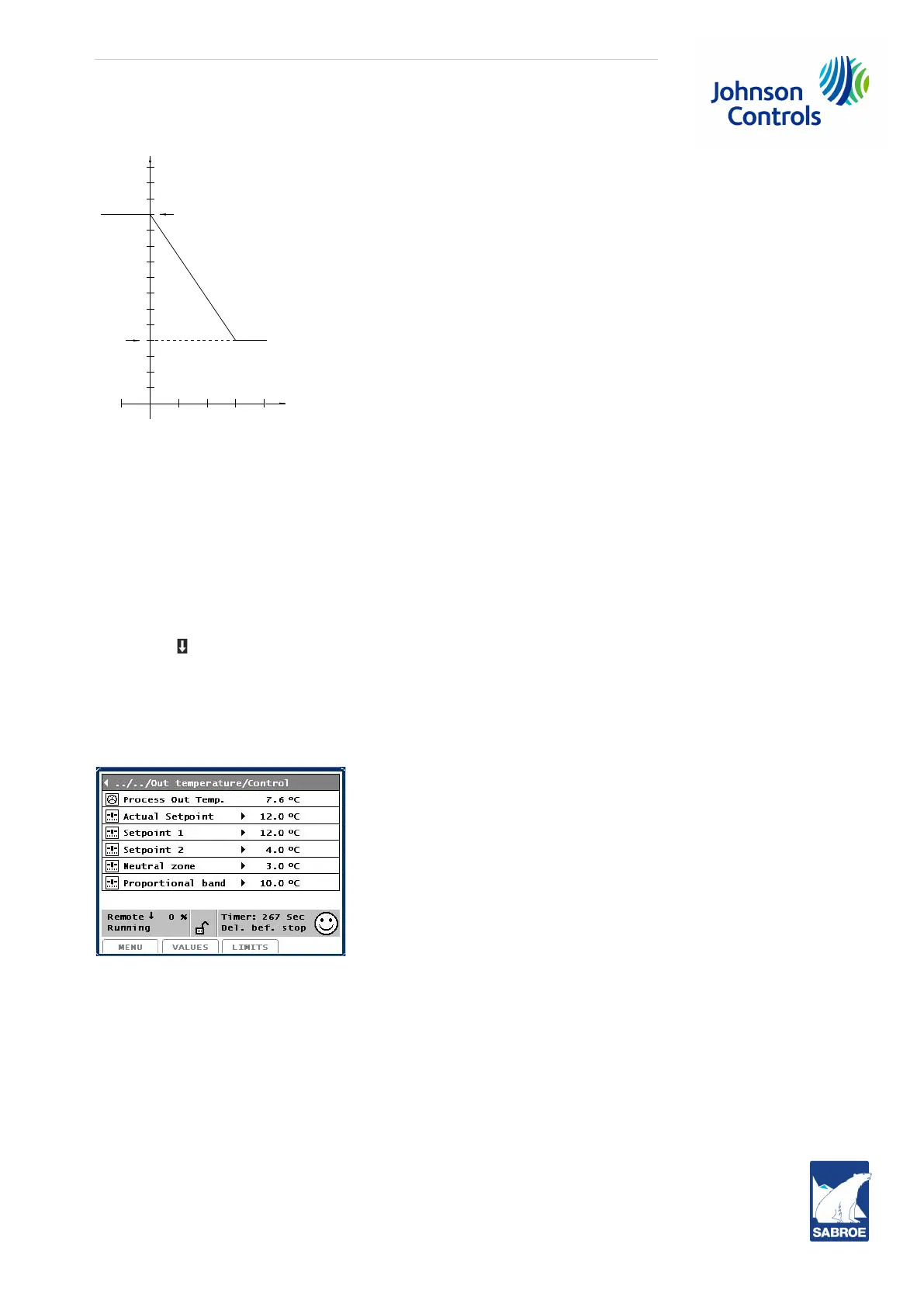
Fig. 15: Climate compensation, example 1
The settings in the drawing are:
Sp1 = 12°C at To = 0°C and
Sp2 = 4°C at To = 30°C.
Note that Sp1 belongs to the lowest and Sp2 to highest outside temperature.
The straight line in Fig. 15 indicates the inlet temperature variation under influence of the outside
temperature.
Select the menu Control values/Process temp./Process out temp./Control and go to Set point 1 and Set
point 2 with .
Give Set point 1 the value Sp1 = 12°C from Fig. 15.
Give Set point 2 the value Sp2 = 4°C from Fig. 15.
At the same time, set Neutral zone = 3°C and Prop. band = 10°C as starting points. The system is now
adjusted to the desired function. The picture will now look like this:
The Actual Setpoint shows the regulating value of the inlet temperature at that particular moment. If the
outside temperature is 30°C, this value must be 4°C. If the outside temperature is 0°C, the value must
be 12°C. The outside temperature can be seen in % of the measuring range in the picture Control val-
ues/Capacity/Values.
40302010-10
4
2
6
10
12
8
14
Sp 1
Sp2
T out
T inlet

 Loading...

