100
IGNITION
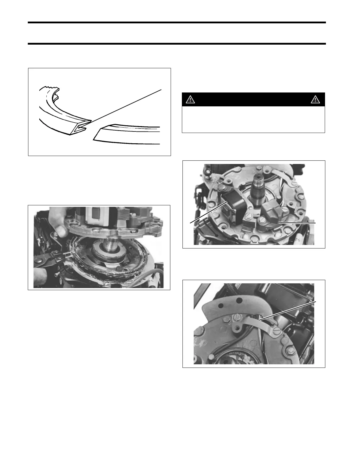
CHARGE COIL AND SENSOR COIL
Lubricate the ignition plate bearing groove with
Moly Lube.
Apply Nut Lock to the threads of the ignition plate
screws. Insert needle-nose pliers into slots in the
ignition plate bearing and compress bearing while
guiding the ignition plate into position.
Align the ignition plate with the retainer plate.
Torque the screws to 25 to 35 in. lbs. (2.8 to 4.0
N·m).
Connect and adjust spark advance link. Refer to
SYNCHRONIZATION AND LINKAGE ADJUST-
MENTS on p. 59.
Check for sufficient slack on ignition component
leads during full advance movement of the ignition
plate.
CHARGE COIL AND
SENSOR COIL
Removal
Remove the screws retaining the ignition compo-
nent that is being replaced.
Remove the wire clamp from the ignition plate.
1. Groove DR2618
32380
1
WARNING
To prevent accidental starting while ser-
vicing, twist and remove all spark plug
leads.
1. Charge coil
2. Sensor coil
32329
1. Wire clamp 32302
21
1