95
IGNITION
IGNITION SYSTEM TESTS
5
Ignition Coil Tests
Ignition Coil Specifications
Resistance Test
Resistance tests may be performed while the igni-
tion coil is still mounted on the powerhead.
STEP 1
Twist and remove the spark plug leads and pri-
mary coil leads from the ignition coil.
Calibrate ohmmeter on appropriate scale. Con-
nect meter black lead to a clean engine ground. If
the coil is not mounted on the engine, connect
meter black lead to ground tab on the coil. Con-
nect meter red lead to coil primary terminal.
• Meter must show 0.1 ± 0.05 ohm
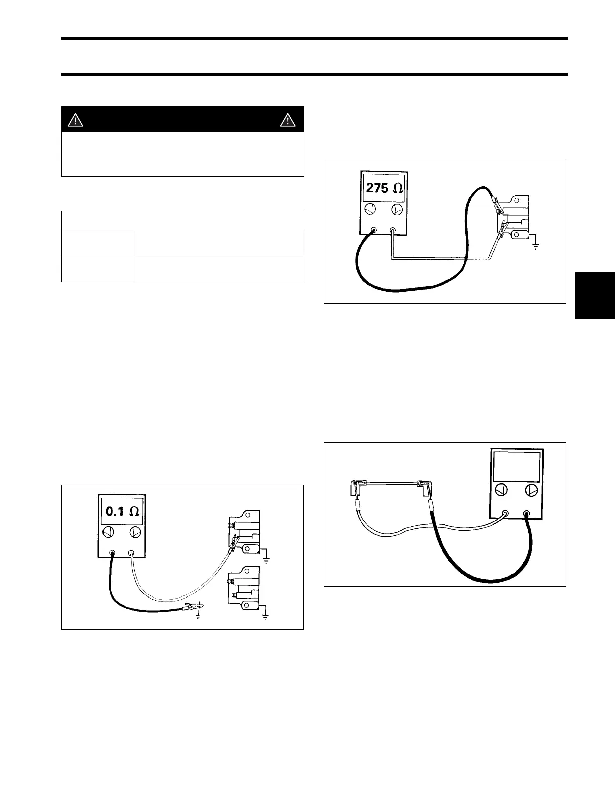
STEP 2
Calibrate ohmmeter on appropriate scale. Con-
nect meter red lead to coil primary terminal. Con-
nect meter black lead to coil spark plug terminal.
• Meter must show 275 ± 50 ohms
STEP 3
Test spark plug leads for continuity. Calibrate
ohmmeter on low ohms scale. Attach one ohmme-
ter lead to each spring terminal. While wiggling
both spark plug covers and entire length of the
spark plug lead, the resistance should remain
near zero. Replace spark plug lead if your test
results vary.
DANGER
To avoid personal injury from electrical
shock, perform all coil tests on a wooden
(or insulated) bench top.
Magneto C.D. Coil Specifications
Primary
Resistance
0.1 ± 0.05
Ω
Secondary
Resistance
275 ± 50
Ω
DR4093
DR4094
DR4081
0 Ω