136
POWERHEAD
ASSEMBLY
ton. The side clearance must not exceed 0.004 in.
(0.10 mm).
Use a machinist's straightedge to check clearance
on the upper tapered rings. Install each ring on its
piston. When checked with the straightedge, there
should be enough ring clearance to allow the
straightedge to touch the piston on both sides of
the ring groove. Make several checks around the
piston.
• If straightedge does not touch piston, remove
the ring and clean ring groove.
ASSEMBLY
IMPORTANT: Proceed slowly. Make no forced
assemblies unless a pressing operation is called
for. All internal components must be perfectly
clean and lightly coated with Johnson/Evinrude
Outboard Lubricant.
Using Wrist Pin Pressing Pin, P/N 392511, seat a
new retaining ring in groove of the piston.
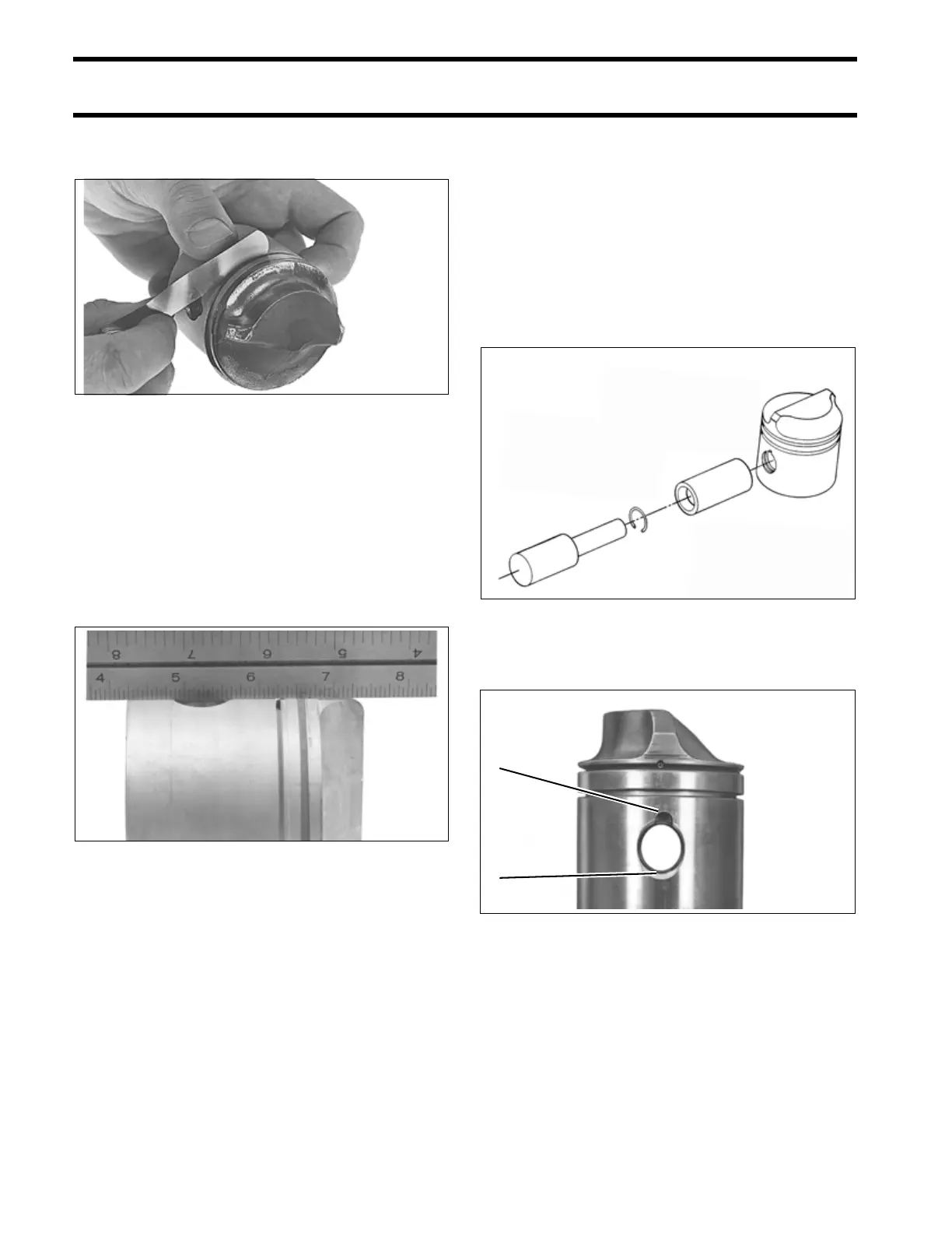
IMPORTANT: Gap of the ring must be posi-
tioned opposite notch in the piston.
32407
12907
DR2661
1. Gap of retaining ring
2. Notch in piston
COB1132
2
1