70
ELECTRICAL
CHARGING SYSTEM TESTS
Stator Resistance Tests
Disconnect the battery cables at the battery.
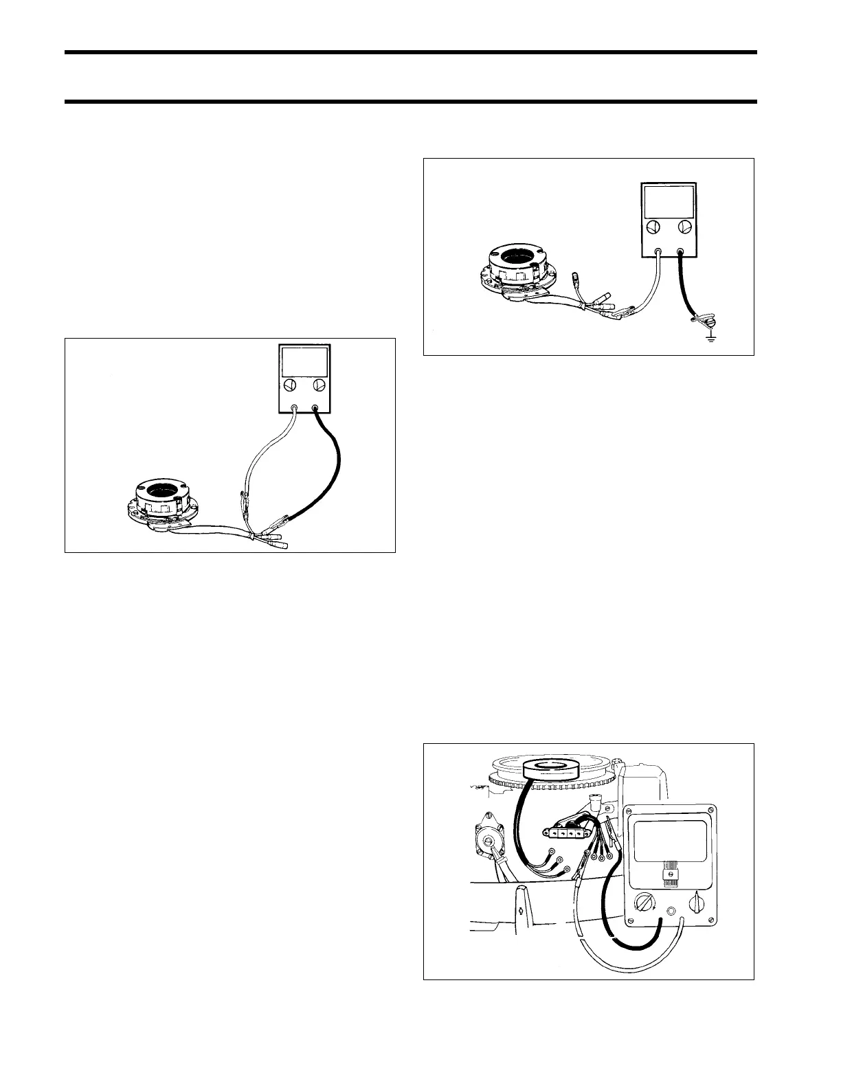
Disconnect all stator leads.
Calibrate ohmmeter on appropriate scale. Con-
nect meter leads between the two stator yel-
low/gray leads.
• Ohmmeter must show a low reading.
• If ohmmeter shows a high reading, repair lead
between the two yellow/gray connectors, or
replace stator.
Connect meter leads between the yellow and yel-
low/gray stator leads.
• Ohmmeter must show 0.80 to 0.90 ohms.
Connect meter leads between the yellow and yel-
low/blue stator leads.
• Ohmmeter must show 0.80 to 0.90 ohms.
Connect meter leads between yellow/blue and
one yellow/gray lead.
• Ohmmeter must show 1.5 to 1.7 ohms.
To check stator for a grounded condition, connect
one meter lead to a clean engine ground and the
other lead alternately to the yellow/blue, yellow,
and yellow/gray stator leads.
• Ohmmeter should show a high reading.
• If ohmmeter shows a low reading, stator is
grounded.
If a stator lead is grounded, repair it or replace the
stator assembly.
Rectifier Resistance Tests
Disconnect the battery cables at the battery.
STEP 1
Disconnect all rectifier leads from terminal board.
Calibrate ohmmeter on appropriate scale. Con-
nect one lead to a clean engine ground. Connect
the other lead to the rectifier yellow/gray lead.
Note the reading. Reverse the ohmmeter connec-
tions or press the "reverse polarity" button and
note the reading. Perform the same procedure on
the yellow and yellow/blue rectifier leads. Note the
readings.
• A high reading in one direction and a low read-
ing in the other direction indicates the diode is
OK.
• Two high readings or two low readings indicate
the diode is damaged.
DR4816
%
DR4818
DR4157
∞
%