92
IGNITION
IGNITION SYSTEM TESTS
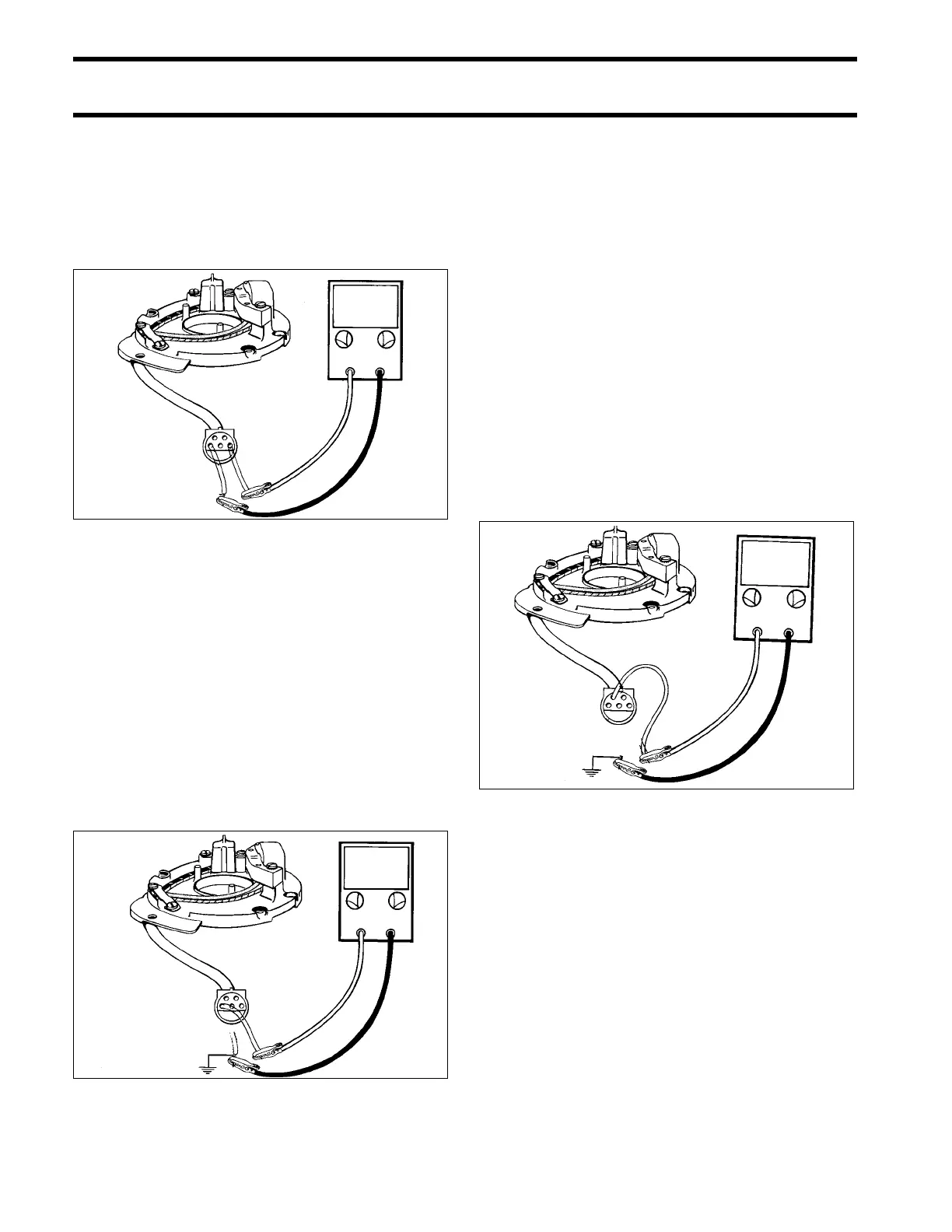
STEP 3
IMPORTANT: All ohmmeter tests must be per-
formed with the engine NOT running.
Insert jumper wires in ignition plate connector, ter-
minals "A" and "D."
Calibrate ohmmeter on appropriate scale. Con-
nect between jumpers. Meter must show:
• 9.9/15 R – 900 ± 100 ohms.
• 9.9/15 (accessory stator, electric) – 760 ± 80
ohms.
To test for a grounded condition, connect ohmme-
ter, alternately, between each jumper and a clean
engine ground.
• Any needle movement indicates charge coil or
leads are grounded.
• Locate and repair ground, or replace charge
coil.
Complete all circuits disconnected during this test.
Sensor Coil Test
STEP 1
Disconnect 5-pin Amphenol connector between
ignition plate and power pack.
Set peak-reading voltmeter to:
• 9.9/15 – "NEG" and "50," or "SEN" and "50" on
Stevens CD-77 meter.
Alternately, connect voltmeter between ignition
plate connector terminals "B," "C," and a clean
engine ground. Crank engine and observe meter
at each connection.
• Any reading indicates sensor coil or leads are
grounded.
• Locate and repair ground, or replace sensor
coil.
• If no reading is indicated, go to STEP 2.
DR4620
DR4619
Ω
∞
DR4621
0 V