93
IGNITION
IGNITION SYSTEM TESTS
5
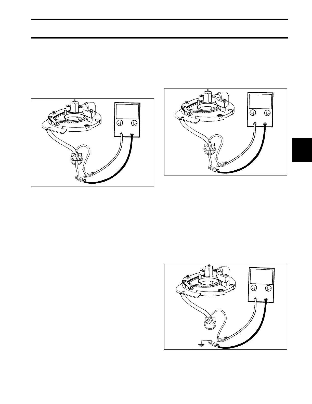
STEP 2
Set peak-reading voltmeter to:
• 9.9/15 – "NEG" and "50," or "SEN" and "50" on
Stevens CD-77 meter.
Attach voltmeter black lead to ignition plate con-
nector, terminal "C." Attach meter red lead to ter-
minal "B."
Crank engine and observe meter.
• If meter shows 1.5 V or higher, go to Power
Pack Cranking Output on p. 94.
• If meter shows less than 1.5 V, check condition
of wiring and connectors.
• If wiring and connector condition is good, go to
STEP 3.
STEP 3
IMPORTANT: All ohmmeter tests must be per-
formed with the engine NOT running.
Insert jumper wires in ignition plate connector, ter-
minals "B" and "C."
Calibrate ohmmeter on appropriate scale. Con-
nect between jumpers.
• Meter must show 40 ± 10 ohms.
To test for a grounded condition, connect ohmme-
ter, alternately, between each jumper and a clean
engine ground.
• Any needle movement indicates sensor coil or
leads are grounded.
• Locate and repair ground, or replace sensor
coil.
Complete all circuits disconnected during this test.
DR4622
≥ 1.5 V
DR4622
DR4621
40 Ω
Ω