87
IGNITION
COMPONENTS
5
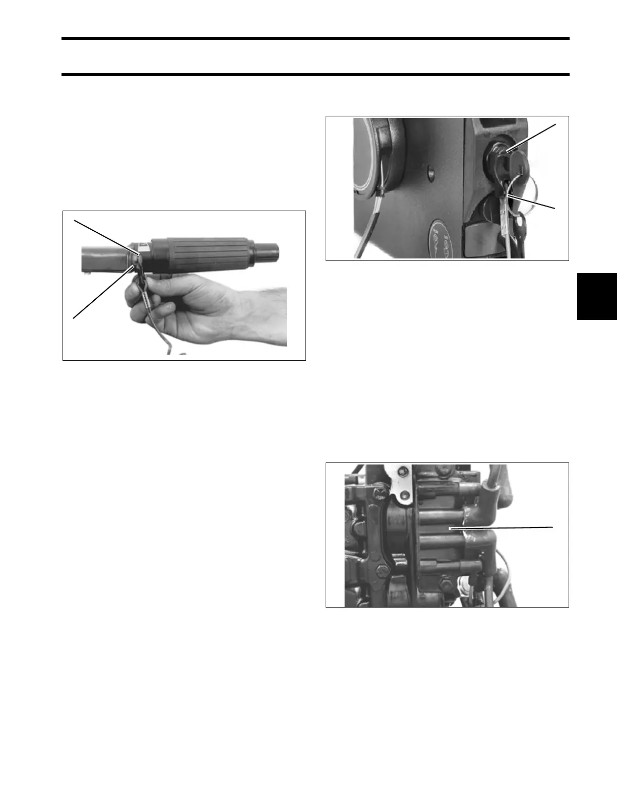
Stop Button
The stop button, and emergency stop switch are
connected to the power pack through the engine
wiring harness. When activated, these switches
direct the power pack output to ground, stopping
the ignition system.
The steering handle contains a combination stop
switch/emergency stop device.
When the clip and lanyard assembly is removed,
the emergency stop device is in the STOP posi-
tion.
When the clip and lanyard assembly is installed,
the emergency stop device is in the RUN position.
To stop the engine when the clip and lanyard
assembly is in place, press the stop button
inward until the engine stops.
Key Switch
A combination key switch and emergency stop
switch is connected to the power pack through the
engine wiring harness (remote electric models).
When activated, this switch directs power pack
output to ground, stopping the ignition system.
IMPORTANT: This emergency stop switch clip
turns the key from ON to OFF as it is removed. It
does not electrically disarm the ignition system.
The key switch, ignition system, and starting cir-
cuit are all fully functional after the emergency
stop switch clip has been removed.
Ignition Coil
The ignition coil consists of two windings of wire
wrapped around a compacted ferrite core. The
coil has primary and secondary terminal connec-
tions and a ground plate.
Through mutual induction, the ignition coil trans-
forms the ignition module output to as much as
40,000 V to fire the spark plugs. There is one igni-
tion coil per cylinder.
1. Stop button
2. Emergency stop switch
24331
2
1
1. Key switch
2. Emergency stop switch clip
31545
9.9/15 Model
1. Dual ignition coil
32322
1
2
1