72
ELECTRICAL
ELECTRIC STARTER TESTS
STEP 4
With the engine running at 1000 RPM, check for
voltage between the instrument harness gray lead
and black lead at the dash.
• If voltmeter shows 0 V, go to STEP 5.
• If voltmeter shows more than 8 V, replace the
tachometer.
STEP 5
With the engine running at 1000 RPM, check for
voltage at the engine terminal board gray connec-
tion.
• If voltmeter shows 0 V, replace or repair the rec-
tifier.
If the voltmeter shows 8 V or higher, check the
instrument harness and engine harness gray cir-
cuit for an open.
ELECTRIC STARTER
TESTS
Start Switch Test
Disconnect the two starter switch leads.
Connect ohmmeter between switch leads. Acti-
vate switch. Meter must indicate resistance as fol-
lows:
• Low resistance reading when switch is pressed.
• High resistance reading when switch is
released.
Replace the start switch if test results are not cor-
rect.
Start Circuit Voltage Test
IMPORTANT: Outboard must be in NEUTRAL
throughout test procedure and battery must be
fully charged.
STEP 1
Connect voltmeter red lead to battery positive (+)
terminal. Connect voltmeter black lead to battery
negative (–) terminal. Check the battery voltage.
• If the voltmeter shows 12 V, go to STEP 2.
• If the voltmeter shows 0 V, test the battery.
STEP 2
Move the voltmeter black lead to the rectifier ter-
minal ground. Check the voltage between battery
positive (+) terminal and rectifier terminal ground.
• If the voltmeter shows 12 V, go to STEP 3.
• If the voltmeter shows 0 V, test the negative (–)
battery cable.
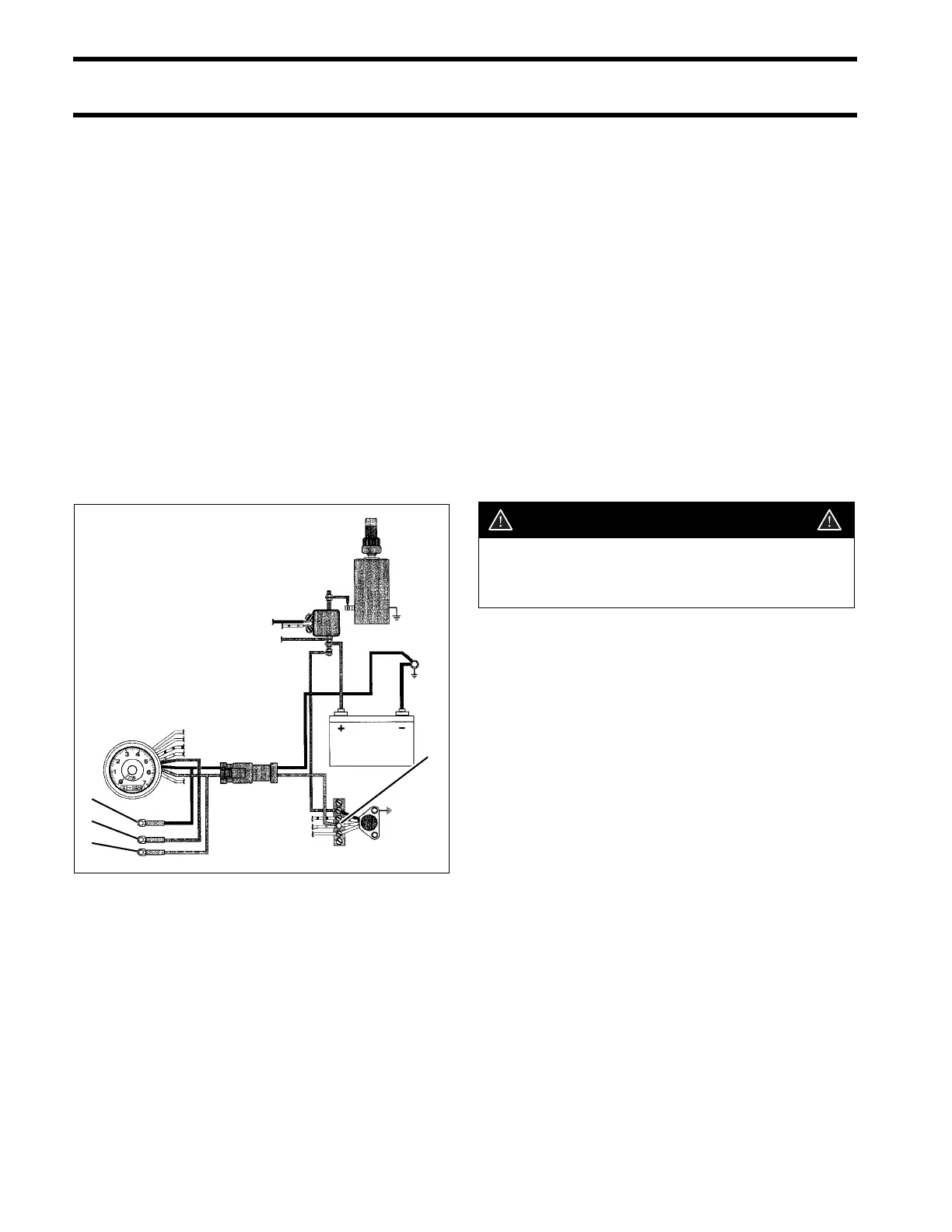
1. Purple lead
2. Black lead
3. Gray lead
4. Terminal board gray connection
DRC6297
4
2
1
3
WARNING
Avoid accidental starting while testing;
disconnect the starter cable from the
starter terminal.