76
ELECTRICAL
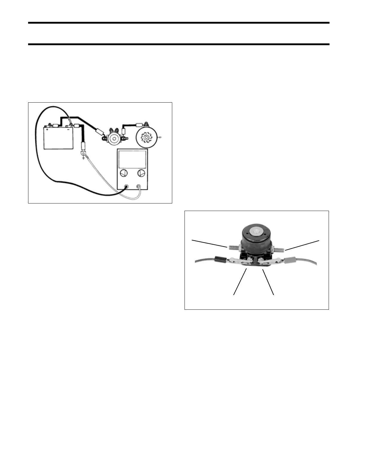
ELECTRIC STARTER TESTS
STEP 4
Connect voltmeter positive (+) lead to battery neg-
ative (–) lead common powerhead ground screw.
Connect voltmeter negative (–) lead to battery
negative (–) post. Turn key switch to START.
• Voltage reading must not be more than 0.3 volt.
STEP 5
Clean and tighten, or replace, any connection,
cable, or other component that does not meet the
specified values.
Starter Solenoid Test
IMPORTANT: All engine wiring must be discon-
nected from the solenoid before proceeding.
STEP 1
Connect one ohmmeter lead to terminal (A) and
the other lead to terminal (B).
• Ohmmeter must show a high reading.
• If ohmmeter shows a low reading, replace the
solenoid.
STEP 2
With the ohmmeter still connected, attach a posi-
tive (+) battery jumper to terminal (C) and a nega-
tive (–) battery jumper to terminal (D). The
solenoid should close with an audible click.
• Ohmmeter must show a low reading.
• If ohmmeter shows a high reading, replace the
solenoid.
After installing the solenoid, coat all wires and ter-
minals with Black Neoprene Dip.
DRC4032
≤ 0.3V
24082
BA
CD