109
FUEL SYSTEM
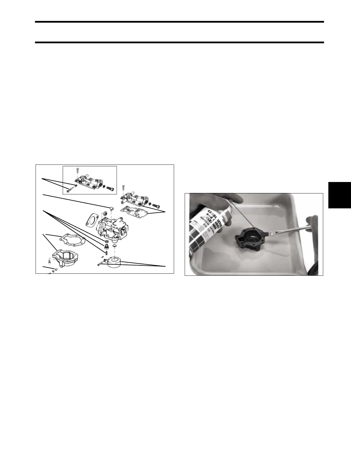
CARBURETOR SERVICE
6
HR Models Only
Remove the low-speed needle and spring from
the carburetor body cover.
All Models
Remove the six cover screws. Lift the cover and
gasket off the carburetor body.
Remove the seven float chamber screws and the
float chamber and gasket.
Remove the hinge pin, float, and inlet valve
assembly.
Remove the high-speed orifice. If necessary,
remove the air vent.
Refer to Cleaning and Inspection on p. 109.
Cleaning and Inspection
IMPORTANT: Do not clean carburetor or its
components by submerging in strong carburetor
cleaner or hot soaking tank. Strong cleaners might
damage components or remove sealing com-
pounds.
Before inspection, all carburetor components
must be thoroughly clean.
• Carburetor must be completely disassembled.
• Clean parts with Carburetor and Choke
Cleaner.
• Use a clean bristle brush to remove gum or var-
nish deposits.
• Blow dry with shop air of not more than 25 psi
(172 kPa). When drying passages, direct the
flow of shop air opposite to the direction of fuel
flow.
Float Valve Assembly
Inspect the inlet needle and float valve seat.
• Check the float for signs of oil or gasoline satu-
ration.
• Check the float valve seat for nicks, scratches,
or distortion.
• Check the inlet needle tip for grooves, nicks,
scratches, or distortion.
1. Low speed needle and spring (10RH models only)
2. Carburetor body cover and gasket
3. Float chamber and gasket
4. Hinge pin and float
5. Inlet valve assembly
6. High-speed orifice
7. Air vent
002535
2
4
1
7
5
3
6
33953