8. Taking care not to touch the leads, pins, or solder connecons, place one hand underneath the RE
module to support it and slide it completely out of the chassis.
9. Place the RE module in the anstac bag or on the anstac mat.
CAUTION: Do not stack hardware components on one another aer you remove
them. Place each component on an anstac mat resng on a stable, at surface.
NOTE: To maintain proper airow through the chassis, do not leave an Switch Fabric module
(SF module) installed in the chassis without an RE module for extended periods of me. If you
remove an RE module, install a replacement RE module as soon as possible.
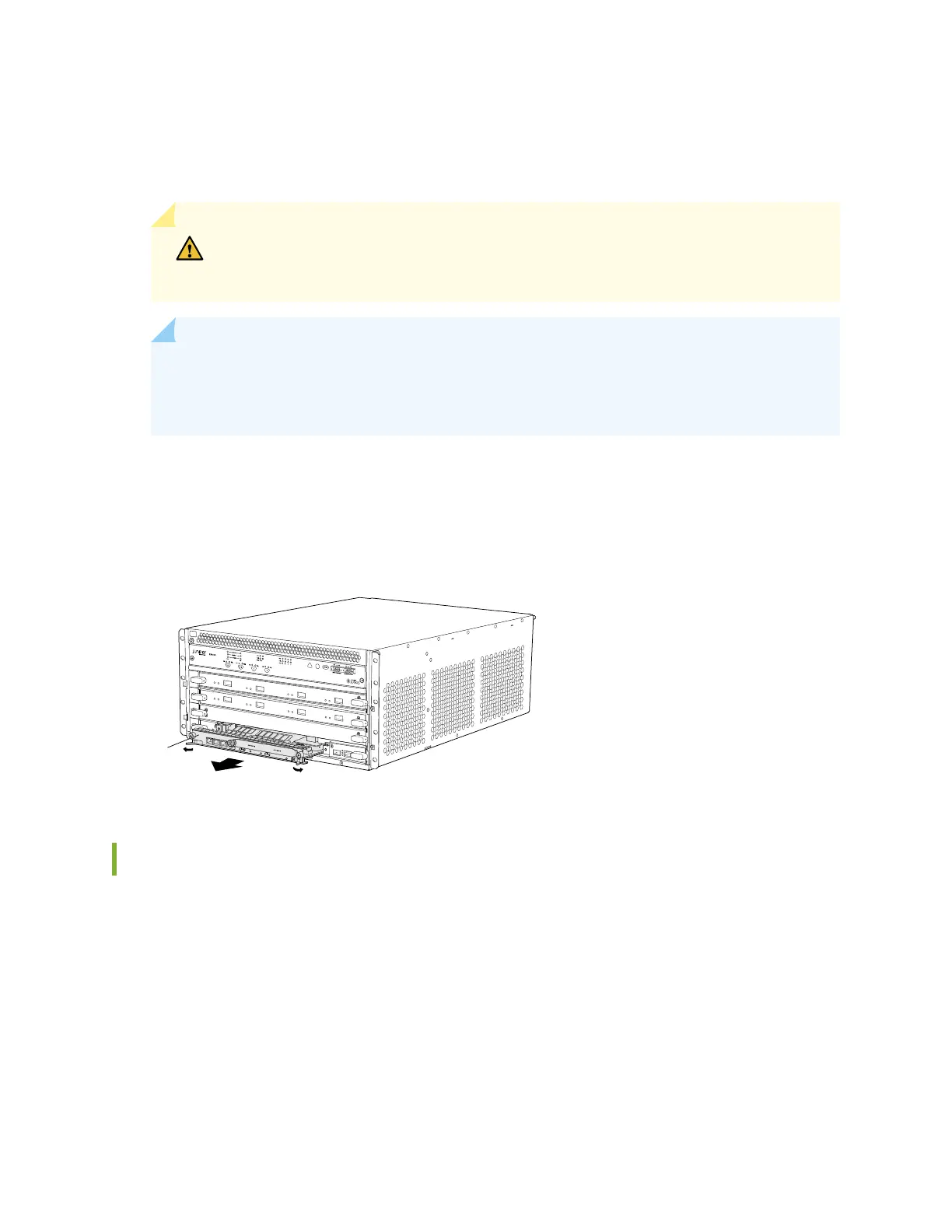
Figure 71 on page 227 shows removing an RE module from an EX9204 switch. The procedure is the
same for all EX9200 switches.
Figure 71: Removing an RE Module from an EX9200 Switch
g022040
0
2
1
0
1
ESD
Routing
Engine
Installing an RE Module in an EX9200 Switch
Before you begin installing an RE module in an EX9200 switch:
• Ensure you understand how to prevent electrostac discharge (ESD) damage. See
Prevenon of
Electrostac Discharge Damage
.
Ensure that you have the following parts and tools available to install an RE module:
• ESD grounding strap
• Phillips (+) screwdrivers, number 1 and 2
227