Figure 7 on page 30 shows the cra interface in an EX9204 switch. Figure 8 on page 30 shows the
cra interface in an EX9208 switch. Figure 9 on page 31 shows the cra interface in an EX9214
switch.
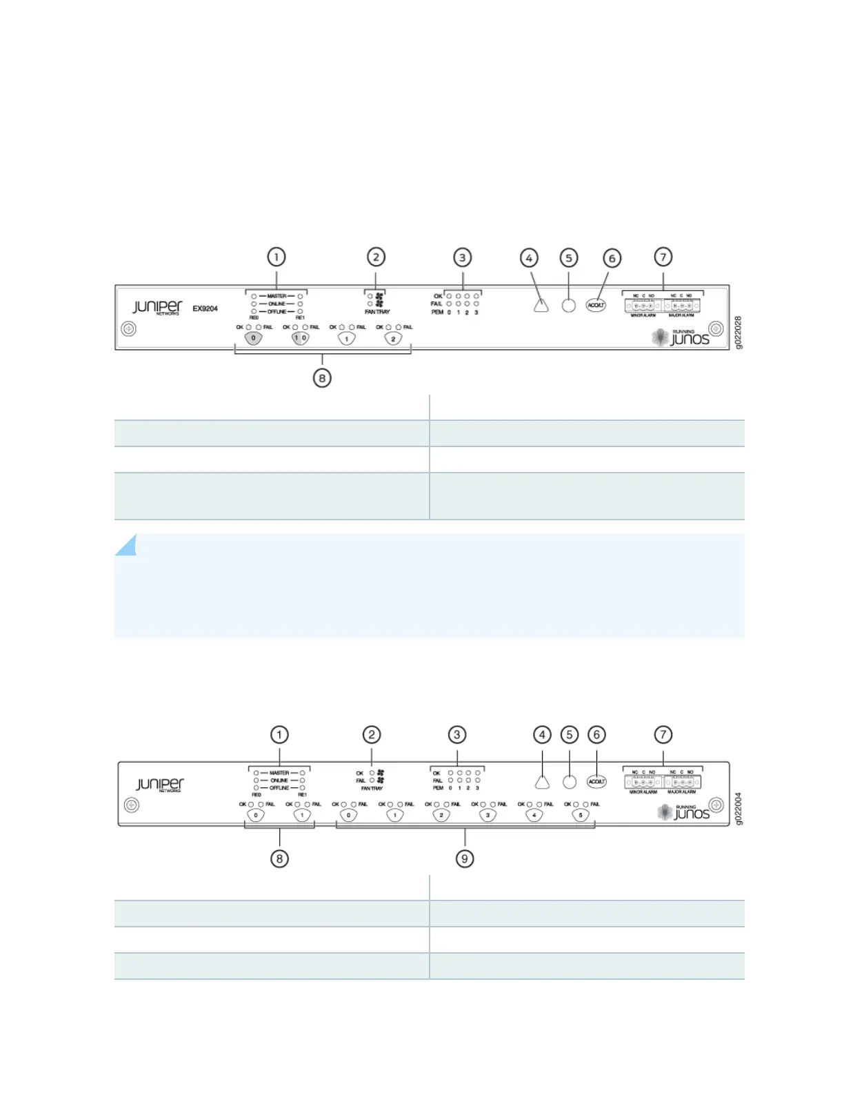
Figure 7: Cra Interface in an EX9204 Switch
1—
Host subsystem LEDs
5—
Major alarm LED
2—
Fan LEDs
6—
Alarm cuto/lamp test buon
3—
Power supply LEDs
7—
Alarm relay contacts
4—
Minor alarm LED
8—
LEDs and control buons for Switch Fabric
and Line cards
NOTE: You can install a line card or an SF module in the mulfunconal slot labeled 1|0 in
EX9204 switches. The corresponding LED displays informaon depending on the hardware
installed in that slot.
Figure 8: Cra Interface in an EX9208 Switch
1—
Host subsystem LEDs
6—
Alarm cuto/lamp test buon
2—
Fan LEDs
7—
Alarm relay contacts
3—
Power supply LEDs
8—
Switch Fabric LEDs and control buons
4—
Minor alarm LED
9—
Line card LEDs and control buons
30