5—
Major alarm LED
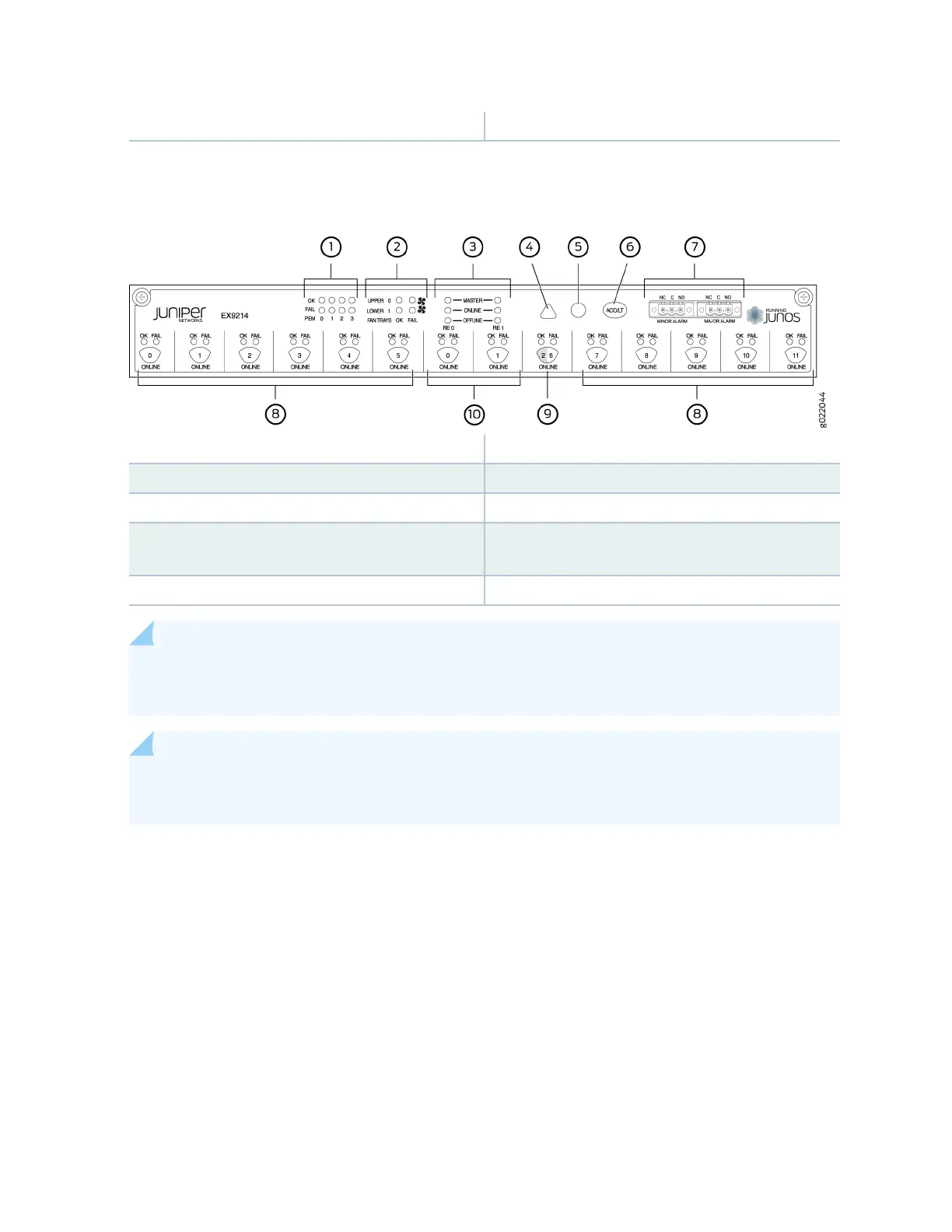
Figure 9: Cra Interface in an EX9214 Switch
1—
Power supply LEDs
6—
Alarm cuto/lamp test buon
2—
Fan LEDs
7—
Alarm relay contacts
3—
Host subsystem LEDs
8—
Line card LEDs and control buons
4—
Minor alarm LED
9—
Switch Fabric/line card LED and control
buon
5—
Major alarm LED
10—
Switch Fabric LEDs and control buons
NOTE: You can install a line card or a Switch Fabric module (SF module) in slot nine—labeled 2 |
6. The corresponding LED displays informaon depending on the hardware installed in that slot.
NOTE: At least one Switch Fabric module (SF module) with a Roung Engine module (RE module)
must be installed in the switch for the cra interface to obtain power.
The cra interface has the following components:
Host Subsystem LEDs
Each host subsystem (RE module with SF module) has three LEDs, located on the upper le of the cra
interface, to indicate its status. The LEDs grouped with labels RE0 and RE1 show the status of the host
subsystems installed in the switch. Table 7 on page 32 describes the funcons of these LEDs.
31