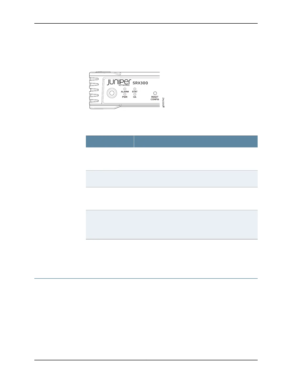
Figure 2 on page 7 shows the LEDs on the front panel.
Figure 2: SRX300 Services Gateway Front Panel LEDs
Table 4 on page 7 lists the front panel LEDs.
Table 4: SRX300 Services Gateway Front Panel LEDs
DescriptionComponent
•
Solid amber (noncritical alarm)
•
Solid red (critical alarm)
•
Off (no alarms)
ALARM
•
Solid green (operating normally)
•
Solid red (error detected)
STAT
•
Solid green (receiving power)
•
Solid red (power failure)
•
Off (no power)
PWR
•
Solid green (all HA links are available)
•
Solid amber (some HA links are unavailable)
•
Solid red (HA links are not functional)
•
Off (HA is disabled)
HA
Related
Documentation
SRX300 Services Gateway Chassis Overview on page 5•
• Understanding the SRX300 Services Gateway Back Panel on page 7
Understanding the SRX300 Services Gateway Back Panel
Figure 3 on page 8 shows the back panel of the SRX300 Services Gateway and
Table 5 on page 8 lists the back panel components.
7Copyright © 2016, Juniper Networks, Inc.
Chapter 2: Chassis Description