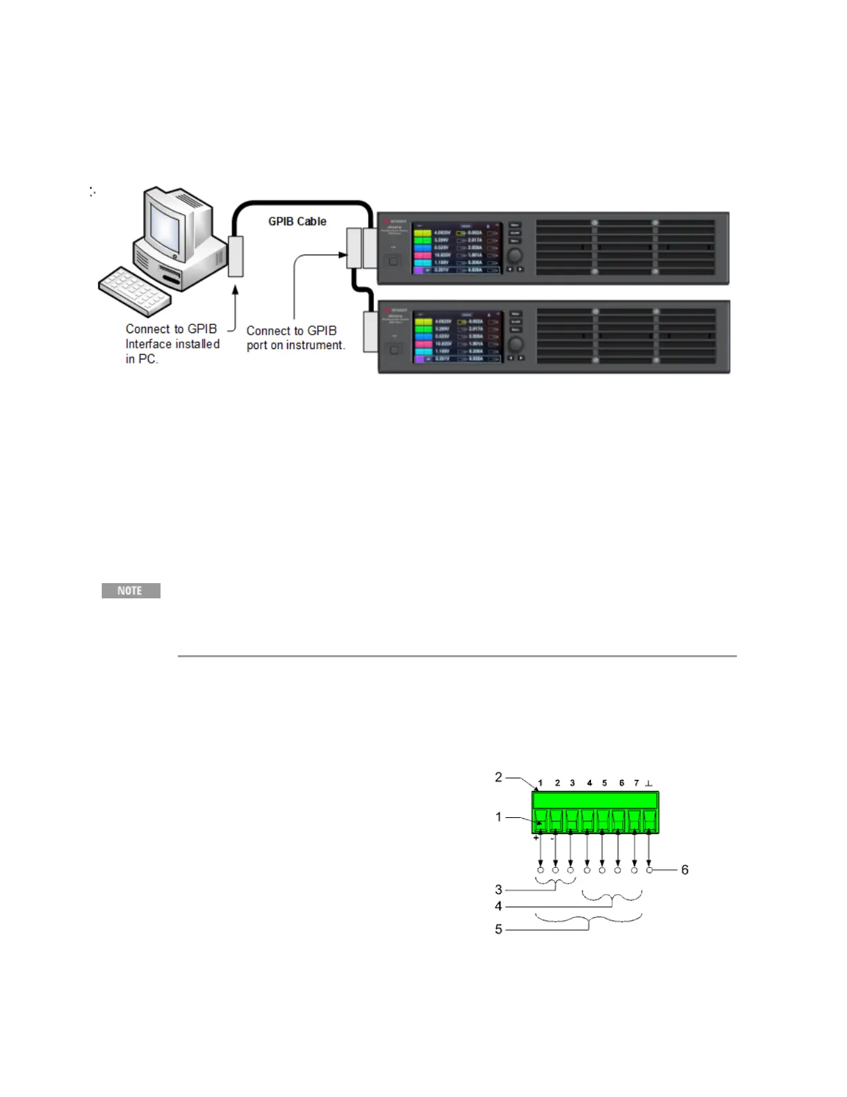
GPIB Connections
The following figure illustrates a typical GPIB interface system. GPIB connections are only available on
units with Option GPB.
1. Connect your instrument to the GPIB interface card using a GPIB interface cable.
2. Use the Connection Expert utility of the Keysight IO Libraries Suite to configure the GPIB card’s
parameters.
3. You can now use Interactive IO within the Connection Expert to communicate with your instru-
ment, or you can program your instrument using the various programming environments.
Digital Port Connections
It is good engineering practice to twist or shield all signal wires to and from the
digital connector. If shielded wire is used, connect only one end of the shield to
chassis ground to prevent ground loops.
An 8-pin connector and a quick-disconnect connector plug are provided for accessing the digital port
functions. Disconnect the connector plug to make your wire connections. The connector plug accepts
wires sizes from AWG 14 (1.5 mm
2
) to AWG 28 (0.14 mm
2
). Wire sizes smaller than AWG 24 (0.25
mm
2
) are not recommended. Strip wire insulation back 7 mm.
1. Insert wires
2. Tighten screws
3. Fault/Inhibit configurable pins (observe INH polarity)
4. Output Couple configurable pins
5. Digital IO-configurable pins
6. Signal common
Information on using the digital port is found under Programming the Digital Port. The electrical
characteristics are described in the Common Characteristics tables.
2 Installing the Instrument
54 Keysight MP4300 Series Operating and Service Guide