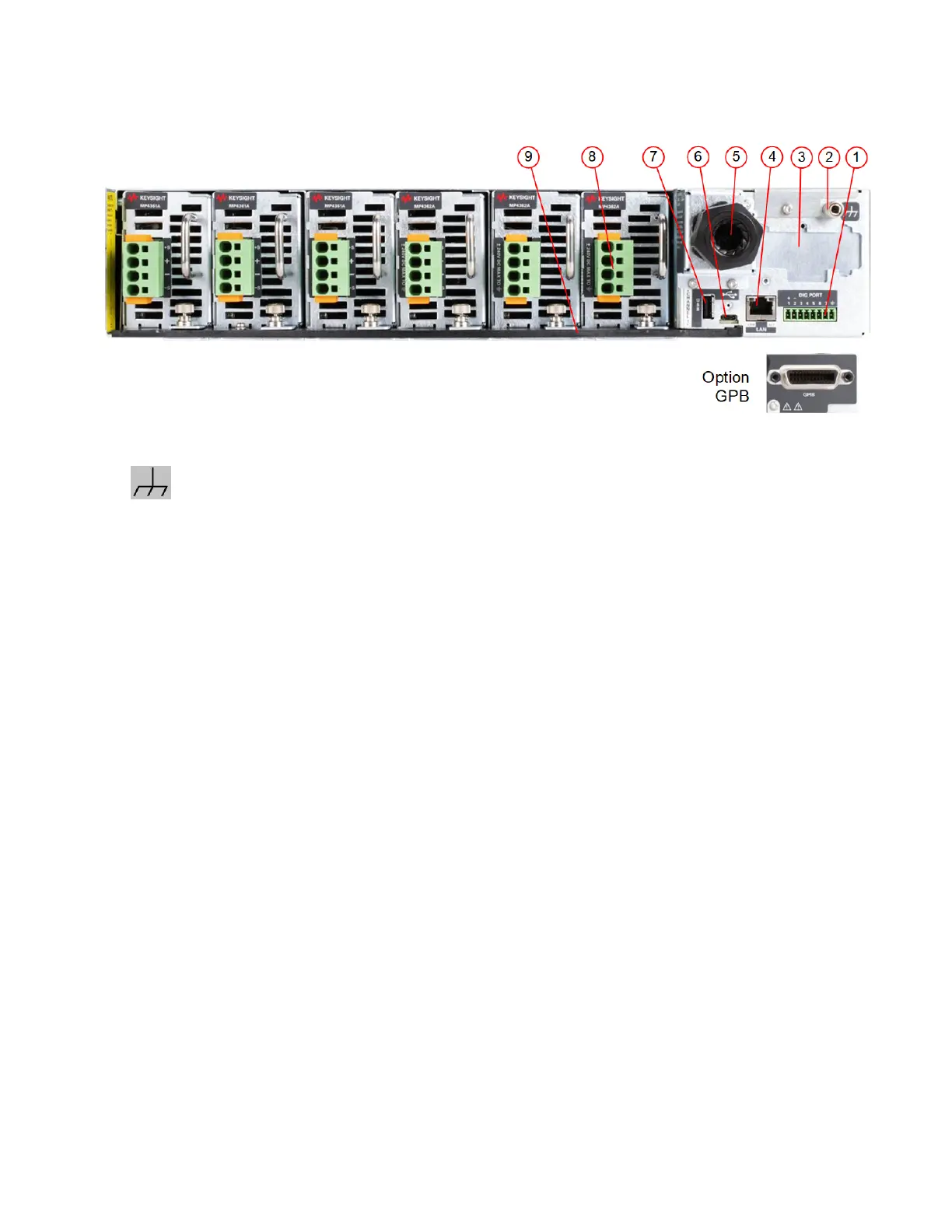
Rear Panel at a Glance
1. Digital IO - Digital IO connector. Pins are user-configurable.
2.
- Auxiliary chassis ground stud. Not for use with ac mains connections.
3. Option cover - Location reserved for Option GPB.
4. LAN - 10/100/1000 Base-T Left LED indicates activity. Right LED indicates link integrity.
5. AC input cover - AC input requires 3-phase L1, L2, L3, connections. A chassis ground stud is loc-
ated under the cover for the ac mains ground connection. The ac input is bi-directional.
6. USB - C - USB- C interface connector. USB - C cable with locking connector recommended.
7. Memory port - Reserved for future use..
8. Module connectors - Includes sense and output connections for each power module. Up to six
single slot modules can be installed in an MPS mainframe.
9. Lockout bar - Must be installed to operate power modules.
1 Quick Reference
16 Keysight MP4300 Series Operating and Service Guide