Installing the Mainframe
Power Module Installation
The information in this section applies if you have purchased an MPS mainframe
without the power modules installed, or if you are adding a power module to the
mainframe.
Equipment Damage Turn the mainframe off and disconnect the ac mains before
installing or removing power modules. Observe all standard electrostatic discharge
precautions before handling electronic components.
Any unused slots must have a filler module installed to ensure proper cooling. In the
following figures, a filler module is installed in slot 6.
Tools required: #2 Phillips (optional) and T10 Torx driver
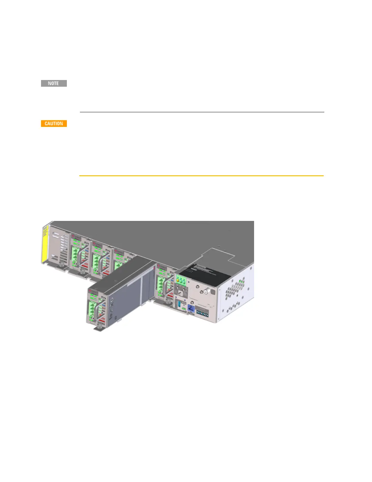
Step 1. Power modules can be installed in any slot. Start by sliding the module into the selected slot. In
the following figure the module is being installed in Slot 2.
Step 2. Loosely tighten the thumbscrew. If the thumbscrew is tightened all the way you will not be able
to install the lockout bar later. Continue installing any other power modules.
Step 3. Install a filler module in any unused slots. In the previous figure, a filler module is shown
installed in slot 6. Note that filler modules are an option that must be ordered along with each
mainframe. Refer to Model Features and Options for more information.
Step 4. Install the lockout bar after all modules have been installed. Slide the lockout bar under the
thumbscrews. The lockout bar ensures that the power modules are not inserted or removed while the
internal high voltage rail is active. Without the lockout bar, the module cannot be powered-on. The
front panel will indicate "No Module Installed".
2 Installing the Instrument
38 Keysight MP4300 Series Operating and Service Guide