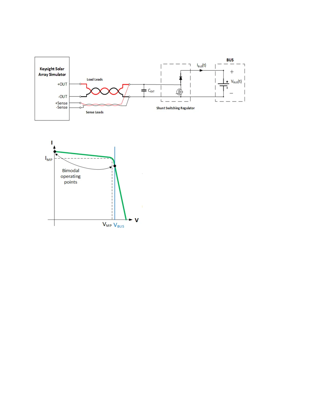
For shunt switching applications, the output typically alternates between two states: as a shunt circuit,
and as a diode coupled to a bus voltage. The following diagram illustrates a typical circuit used for
shunt switching:
Shunt Switching
For applications not described in this section, please consult the factory.
Compensation Modes
The digital control capability of the SAS module allows for flexible, firmware-based compensation
modes which can be tailored for different applications to achieve optimal performance.
DEFAULT Mode
Default mode is intended for initial turn-on and debug when operating in solar array simulation mode.
It is a low performance mode available for initial confirmation of system hardware interconnections to
the DUT and verification of basic SAS mode operation with a static load. It is not optimized for use with
specific DUT types such as DC/DC converters, MPPT trackers or shunt switching control schemes.
l
Not recommended for performance evaluation of DC/DC converter, MPPT, or shunt switching
DUTs
l
Will not provide stable operation with an active DC/DC converter in regulation mode.
l
Recommended for initial verification of hardware configuration with a static load.
Keysight MP4300 Series Operating and Service Guide 77
4 Using the Modular Power System