Paralleled Channel Connections
Parallel Connections
Equipment Damage Only connect power modules that have identical voltage and
current ratings.
Connect the parallel wires at the load, not at the output connectors.
Paralleling outputs provides a greater current capability than can be obtained from a single output.
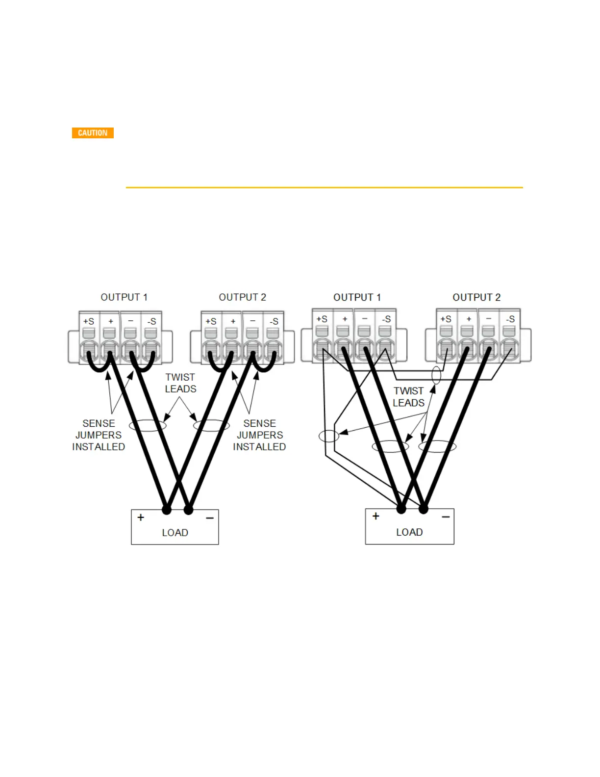
The following figures show how to connect two modules in parallel. The figure on the left illustrates
local sensing. If voltage drop in the load leads is a concern, the figure on the right shows how to
connect the sense leads directly at the load. Note that in both cases, the remote sense terminals must
be connected.
Local sensing
Remote sensing
First program both outputs to the desired output voltage. Then program the current limit of each
output. In Current Priority mode, program the output current of each output to one half of the total
desired output current. Set the voltage limit to a value higher than the expected output voltage.
Effect on Specifications
Specifications for outputs operating in parallel can be obtained from the specifications for single
outputs. Most specifications are expressed as a constant or as a percentage (or ppm) plus a constant.
For parallel operation, the percentage portion remains unchanged while constant portions or any
2 Installing the Instrument
50 Keysight MP4300 Series Operating and Service Guide