General Information
P/N 06-237058-001 1-19 February 2012
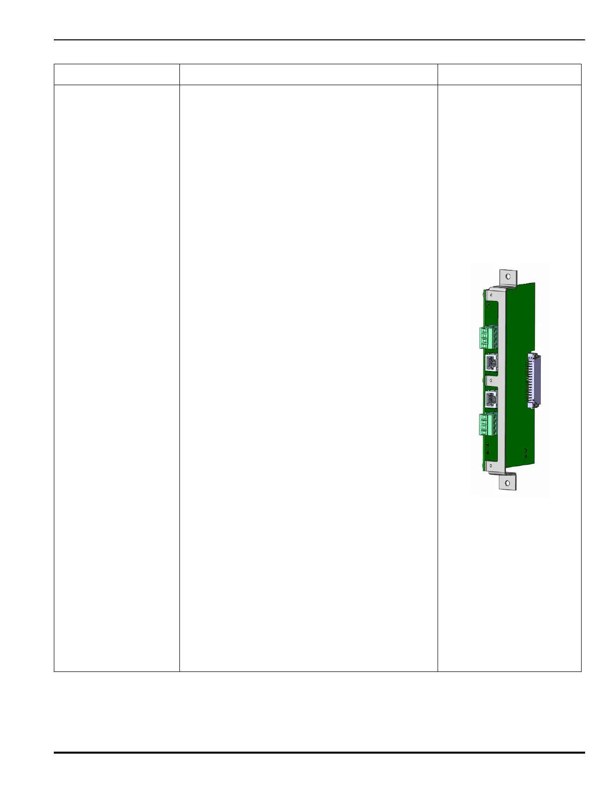
Expansion Card Description Illustration
Digital Alarm
Communicator
Transmitter (DACT)
Card
Refer to Figure 2-34 in
Chapter 2, “Installation”
for a wiring diagram for
the DACT Card.
The Digital Alarm Communicator Transmitter
(DACT) Expansion Card is an optional system
component which transmits system status over phone
lines to a Central Station. The DACT Card includes a
built-in modem and two Loop Start Public Switched
Telephone Network (PSTN) connections for use with
RJ45X phone jacks. Green/yellow status LEDs are
visible from the outside edge of the module, where
green indicates data transmission and yellow
indicates data reception.
The DACT Card is supervised and controlled by the
Main Controller Board using a half-duplex master-
slave polling protocol. The DACT card receives
system status updates, which are stored in memory.
When one or more statuses change, the DACT
initiates a trasmission to the Central Station (over one
or both phone lines). Main Controller Board status
changes include:
• System Status Normal
•AC Failure
• Low Battery Voltage
• Alarm Per Point
•System Supervisory
•System Trouble
• Ground Fault
• Notification Appliance Circuits (NAC) Trouble
• Degraded operation due to microprocessor
failure
Additional internal DACT events (not originating from
the Main Controller Board) are also transmitted to the
Central Station. These include:
•RAM Fault
• NOVRAM/Config Fault
• Phone line #1 Trouble detected
• Phone line #2 Trouble detected
• Communication Trouble with MCB
The DACT Card occupies a single slot in the Card
Cage and plugs directly into the backplane. + 24 Vdc
power is supplied via the backplane connector.
An ARIES NETLink system can include only one
DACT Card.
Table 1-3. Available Expansion Cards