General Information
February 2012 1-18 P/N 06-237058-001
Expansion Card Description Illustration
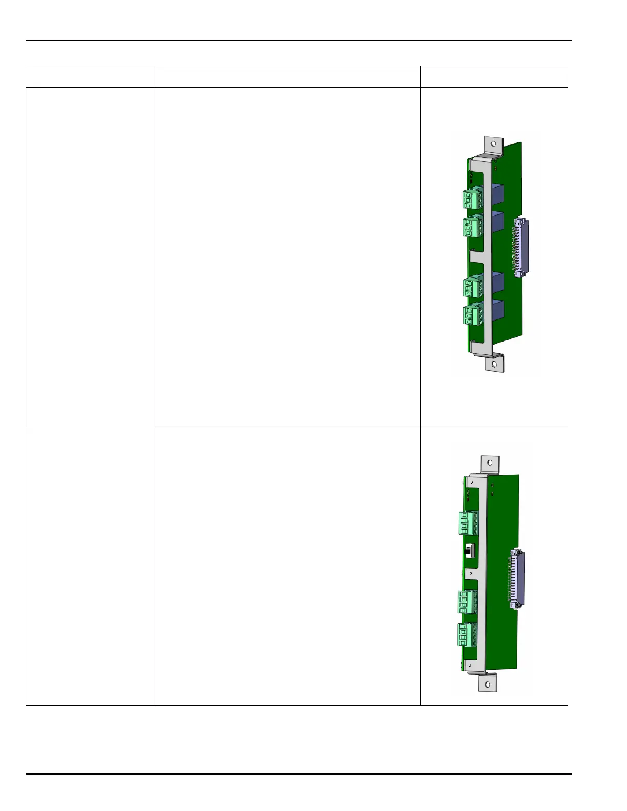
Relay Card
Refer to Figure 2-32 in
Chapter 2, “Installation”
for a wiring diagram for
Relay outputs.
Adding a Relay Expansion Card expands the number
of available programmable relays. The Relay Card is
equipped with four Form C floating relay contacts.
Each relay is independently-driven and can be pre-
programmed to change state for all states of Alarm,
Trouble and Supervisory conditions. Red and green/
yellow status LEDs are visible from the outside edge
of the module. The ability to isolate an individual
relay output is provided through the system menu.
The relays are normally de-energized, unless
configured for Trouble. A Trouble relay is energized
upon startup and changes state for any Trouble
event, including failure of the Main Controller Board.
Ratings are as follows:
•3 A at 30 Vdc
•3 A at 120 Vac
The Relay Card occupies a single slot in the Card
Cage and plugs directly into the backplane. +24 Vdc
power is supplied via the backplane connector.
There is no limit on the number of Relay Cards which
may be included in an ARIES NETLink system
(dependent only on how many slots are available in
the Expansion Card Cage(s).
City Tie Card
Refer to Figure 2-33 in
Chapter 2, “Installation”
for a wiring diagram for
the City Tie Card.
The City Tie Expansion Card provides connection and
operation for three independently-operated signaling
circuits used to connect to Municipal Tie inputs:
• Local Energy output
• Shunt-Type Master Box output
• Reverse Polarity output
The City Tie Expansion Card occupies a single slot in
the Card Cage and plugs directly into the backplane.
+24 Vdc power is supplied via the backplane
connector.
An ARIES NETLink system can include only one City
Tie Card.
Table 1-3. Available Expansion Cards