General Information
P/N 06-237058-001 1-17 February 2012
Table 1-3. Available Expansion Cards
Expansion Card Description Illustration
Signal Line Circuit
(SLC) Card
Refer to Figure 2-22 and
Figure 2-23 in Chapter 2,
“Installation” for wiring
diagrams for SLC circuits.
A Signal Line Circuit (SLC) is a communications
circuit where each addressable device continuously
transmits its current status and responds to polling
by the Main Controller Board. The SLC receives
control requests from the Main Controller Board and
establishes communications with the field devices.
Status changes from the field devices are reported
back to the Main Controller Board.
Each control unit can support up to a total of eight
SLC loops (two located on the MCB and six individual
SLC Expansion Cards).
Green/yellow communications LEDs (for the
backplane and SLC separately) are visible from the
outside edge of the module, where green indicates
data transmission and yellow indicates data
reception. A green/yellow status LED is also visible,
with green indicating that the module is in an
energized/enabled state and yellow indicating a de-
energized/disabled state.
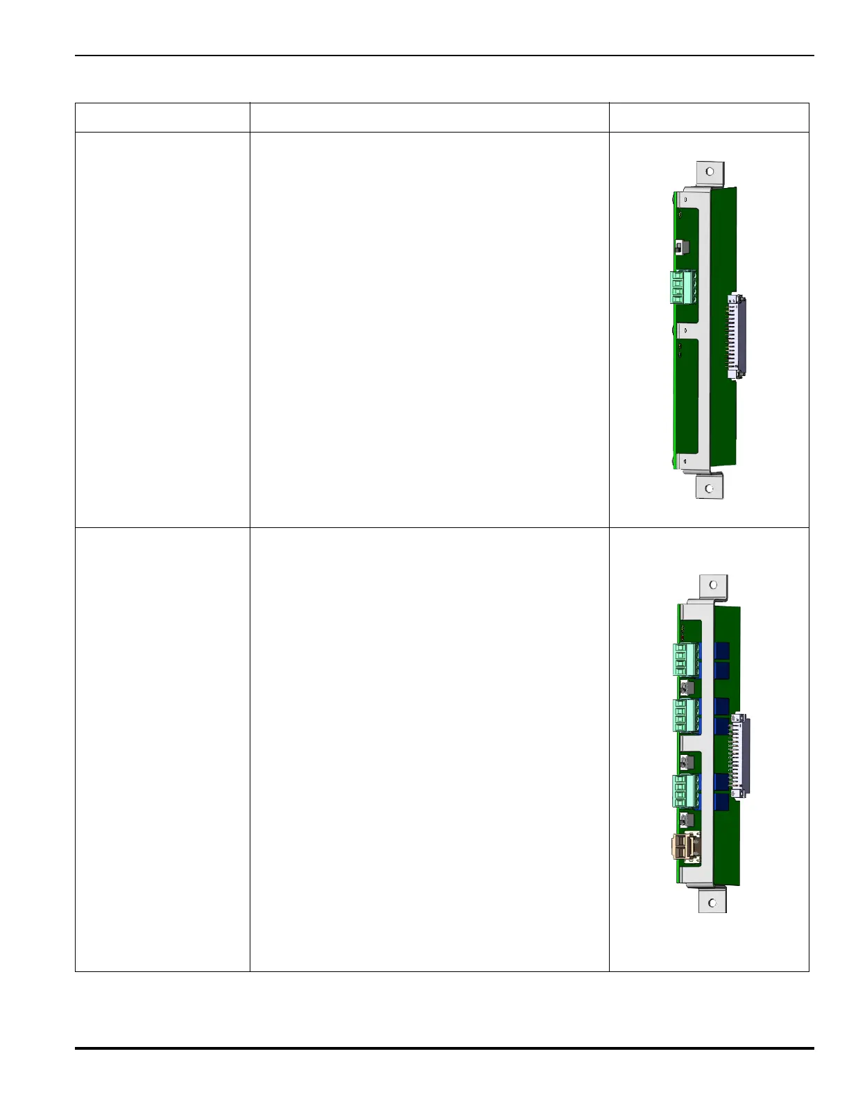
Release/Notification
Appliance (R-NAC)
Circuit Card
Refer to Figure 2-28,
Figure 2-30 and
Figure 2-31 in Chapter 2,
“Installation” for wiring
diagrams for NAC and
releasing circuits.
Adding a Release/Notification Appliance Circuit
(R-NAC) Expansion Card increases the functional
capacity of the ARIES NETLink system by expanding
the number of available signal/releasing circuits to
control fire suppression or notification devices.
These combination Release/Notification Appliance
Circuits can be configured by the user (through the
system menu or remote configuration software) to act
independently as either solenoids/actuators or NACs.
When the circuit is configured as an ARC, the
maximum number of devices/loops supported per
circuit is one solenoid and up to 12 actuators. When
the circuit is configured as a NAC, either
synchronized or non-synchronized strobes can be
supported.
The R-NAC Card occupies a single slot in the Card
Cage and plugs directly into the backplane. +24 Vdc
power is externally provided through a connector
located on the field wiring card edge, not from the
backplane connector.
There is no limit on the number of R-NAC Cards
which may be included in a fully expanded ARIES
NETLink system (dependent only on how many slots
are available).