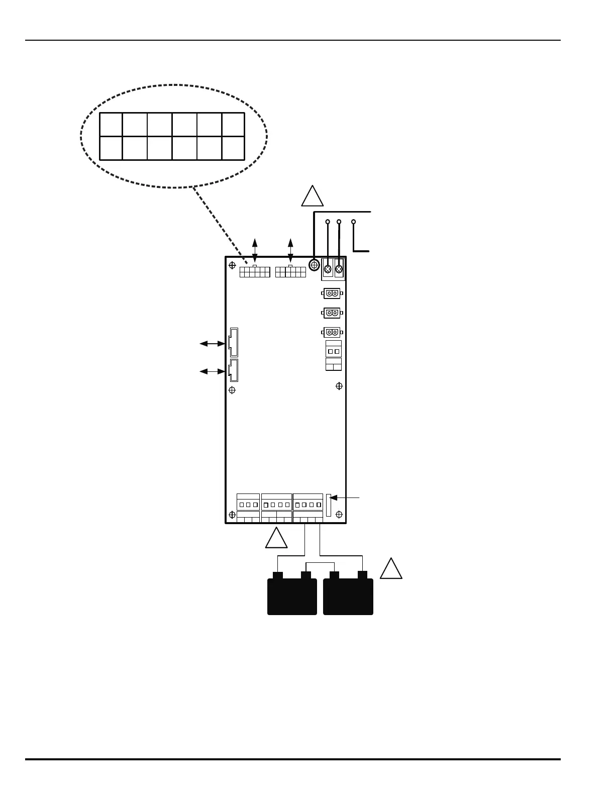
Figure 2-9. Wiring Diagram for Power Management Unit (PMU) Board
BATTERY
-+-+
AUX-1
-
+
-
+
AUX-2
J9 J10
J1
J2
TB1
J3
J4
J5
J15
J12
J13
J11
NO
C
NC
TBL RELAY
+-
24 VDC
NL
White
Black
Green
120 VAC, 50/60 Hz, 3.2 A (single PSU) /
6.4 A (two PSUs)
or
240 VAC, 50/60 Hz, 1.6 A (single PSU) /
3.2 A (two PSUs)
S
To EarthGround stud
on inside of enclosure
Power Management Unit
(PMU)
12-V
Battery
12-V
Battery
+
-
+
-
S
Battery Circuit
Sealed, lead-acid batteries only. Maximum 165 AH.
Replace every 3 years or as recommended by battery manufacturer.
Charging-Circuit Voltage: 27.0 V (nom.)
Charging-Circuit Current: 8.
9
A (max.)
Typical standby operating times are 24 and 90 hours.
Refer to Appendix A for specific battery capacity calculations.
J9 Auxiliary
(AUX-1 and AUX-2)
Special Application
19.2 - 27.6 Vdc
Current: 2.0 (max.) each output
P
F1
Replaceable Fuse
Rating: 15A
To PSU1 To PSU 2
To optional
PMU2 J12
To MCB J2
PMU COMMS
To EarthGround stud
on inside of enclosure
Black
Black
Green
Red Red
White/
Black
White
J1