55
01/13424999386
24 Multi-coloured LED for display of the drive operating state. LED lights up green: Drive moves to “OPEN”;
LED lights up red: Drive moves to “CLOSED”
25 Jumper drive line 1; To select 2- or 3-wire line monitoring
26 Jumper drive line 2; To select 2- or 3-wire line monitoring
27 Wire bridge J1: If the wire is interrupted, the stroke limitation is automatically activated, regardless
the DIP switch position.
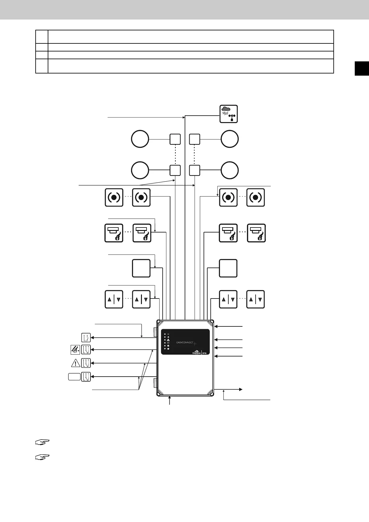
5 Sample wiring diagram
Note: This is only a wiring example.
Note: All cables to the control panel (except the mains supply line) have max. 27 V DC and
must be laid separately from the mains supply line. The respective VDE regulations must be
observedduringlayingofthecables.Thespeciedcablecross-sectionsmustnotbereduced.
Theyarespeciedforanambienttemperatureof20°C.
OK
Wind/rain sensor
up to 200 m IY(St)Y 2 x 2 x 0.8 mm
up to 350 m IY(St)Y 4 x 2 x 0.8 mm
Drives 24 V DC
Channel 1
Drives 24 V DC
Channel 2
IY(St)Y 2 x 2 x 0.8 mm
IY(St)Y 2 x 2 x 0.8 mm
IY(St)Y 2 x 2 x 0.8 mm
IY(St)Y 4 x 2 x 0.8 mm, up to 300 m
Vent switch
Channel 1
FAS contact
Channel 1
Automatic detector
Channel 1
Manual call point
Channel 1
Manual
call point
Channel 2
Automatic
detector
Channel 2
FAS contact
Channel 2
Vent switch
Channel 2
Cable type, see Cable lengths
diagram
NYM-I 3 x 2.5 mm²
Analog IN 4-20 mA
Digital IN (high / low)
Digital IN (high / low)
Digital IN (high / low)
27 V DC / 4 A
Mains supply line
230 V / 50 Hz
NYM-I 3 x 2.5 mm²
EasyConnect+
External
reset button
IY(St)Y 2 x 2 x 0.8 mm
Floating
relay contact
Floating
relay contact
Floating
relay contact
IY(St)Y 2 x 2 x 0.8 mm
EasyConnect+
EN