59
01/13424999386
24 V DC
24 V DC
1 2 3
-
+
-
+
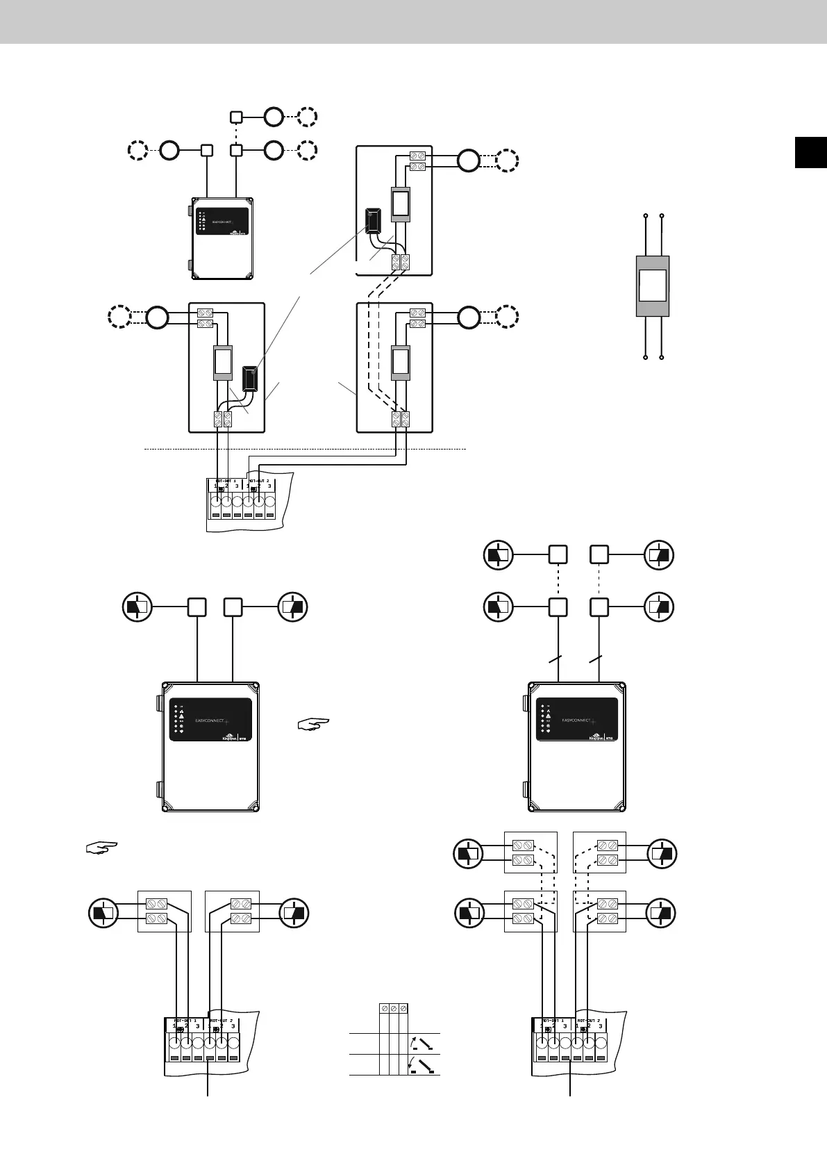
8.2.2 Connection to 24 V DC magnetic clamps
Drive line 2
Drive line 1
Drive
output 2
Drive
output 2
Drive
output 1
Drive
output 1
Drive output 1, 2
24 V DC magnetic
clamp
24 V DC magnetic
clamp
24 V DC magnetic
clamp
24 V DC magnetic
clamp
EasyConnect+
EasyConnect+
22
Note: For this,
DIP switch 7
must be set to ON.
Note: No line monitoring of the drive lines.
Junction box
8.2.1 Connectionofnon-compatibledrives,e.g.lineardriveswithsimpleload
disconnection, with ESM disconnection module (only with 2-wire line monitoring)
Electronic Discon-
nect module ESM
Imax = 4 A
=
M
=
M
Reset
ON
12345678
ON
123456789 10
ON
12345678
Reset
24 V DC
24 V DC
1 2 3
-
-
+
+
-
-
+
+
Smart
Motor
IF
Smart
Motor
IF
Smart
Motor
IF
ESM
brown
brown
brown
red
red
red
black
black
black
Connection to
control panel
Connection to drive
Drive line 1 Drive line 2
Control panel
EasyConnect 20A
+
+
blue
blue
blue
EasyConnect+
ESM
ESM
ESM
24 V DC Drives
Total current
Iges. = 4 A
24 V DC Drives
Total current
Iges. = 4 A
Active motor-
end module
24 V DC Drives
Total current
Iges. = 4 A
Junction box
EasyConnect+
EN