84
01/13424999386
EasyConnect+
16.2 Connection to network board
16.3 CommissioningofseveralnetworkedEasyConnect+controlpanels
► All EasyConnect are connected / networked. At least one area DIP
switch must be set to "ON" on each control panel.
► Supply networked EasyConnect with voltage.
"i.O." is displayed on the 2 x 7-segment display.
►AnEasyConnectfromthenetworkmustbeconguredasmaster
control panel. To do this, press button A on the EasyConnect network
board for longer than 4 seconds and wait 60 seconds.
All addresses of the connected EasyConnect are assigned automatically.
The master control panel monitors all networked devices.
The bus LED in the door is illuminated for all active central panels in the
network.
In the event of a power failure, the BUS LED switches from continuous
display to pulsed (10s) display.
ON
12345678
ON
12345678910
1 2 3 4 51 2 3 4 5
ON
12345678
ON
12345678
> 4 s
Button A
Area DIP
switches
Master Control panel
=
M
=
M
ON
12345678
ON
12341234
ON
SHEVENT
Bus OUTBus IN
=
M
=
M
ON
12345678910
ON
12341234
ON
SHEVENT
Bus OUTBus IN
ON
12345678
ON
12345678910
ON
12345678
ON
123456789 10
ON
12345678
ON
123456789 10
ON
12345678
ON
123456789 10
1 2 3 4 51 2 3 4 5
ON
1234
ON
1234
1 2 3 4 51 2 3 4 5
ON
12345678
1 2 3 4 51 2 3 4 5
ON
12345678
1 2 3 4 51 2 3 4 5
ON
12345678
ON
12345678
ON
123456789 10
ON
12345678
ON
123456789 10
1 2 3 4 51 2 3 4 5
ON
12345678
1 2 3 4 51 2 3 4 5
ON
12345678
ON
12345678
ON
123456789 10
1 2 3 4 51 2 3 4 5
ON
12345678
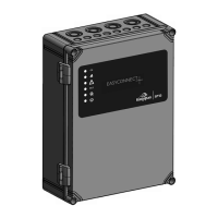
Connection example with 3 networked EasyConnect+ compact control panels in line topology
1
R
R
R
2 3
2-wire shielded
connection cable
2-wire shielded
connection cable
Connection cable
EasyConnect+
Terminating resistor R=100Ωforlinetopology
Forallothertopologies:ConnectaterminatingresistorR=50ΩtoanEasyConnect+locatedascentrallyaspossibleonterminals2and3.
EasyConnect 1
EasyConnect 2 EasyConnect 3
Shield (connect the shield on one side)
Network board
EasyConnect 3
Network board
EasyConnect 2
Network board
EasyConnect 1
Connection cable Terminal
Wire 1 2
Wire 2 3
Shield 1
x
x
xx
x
x
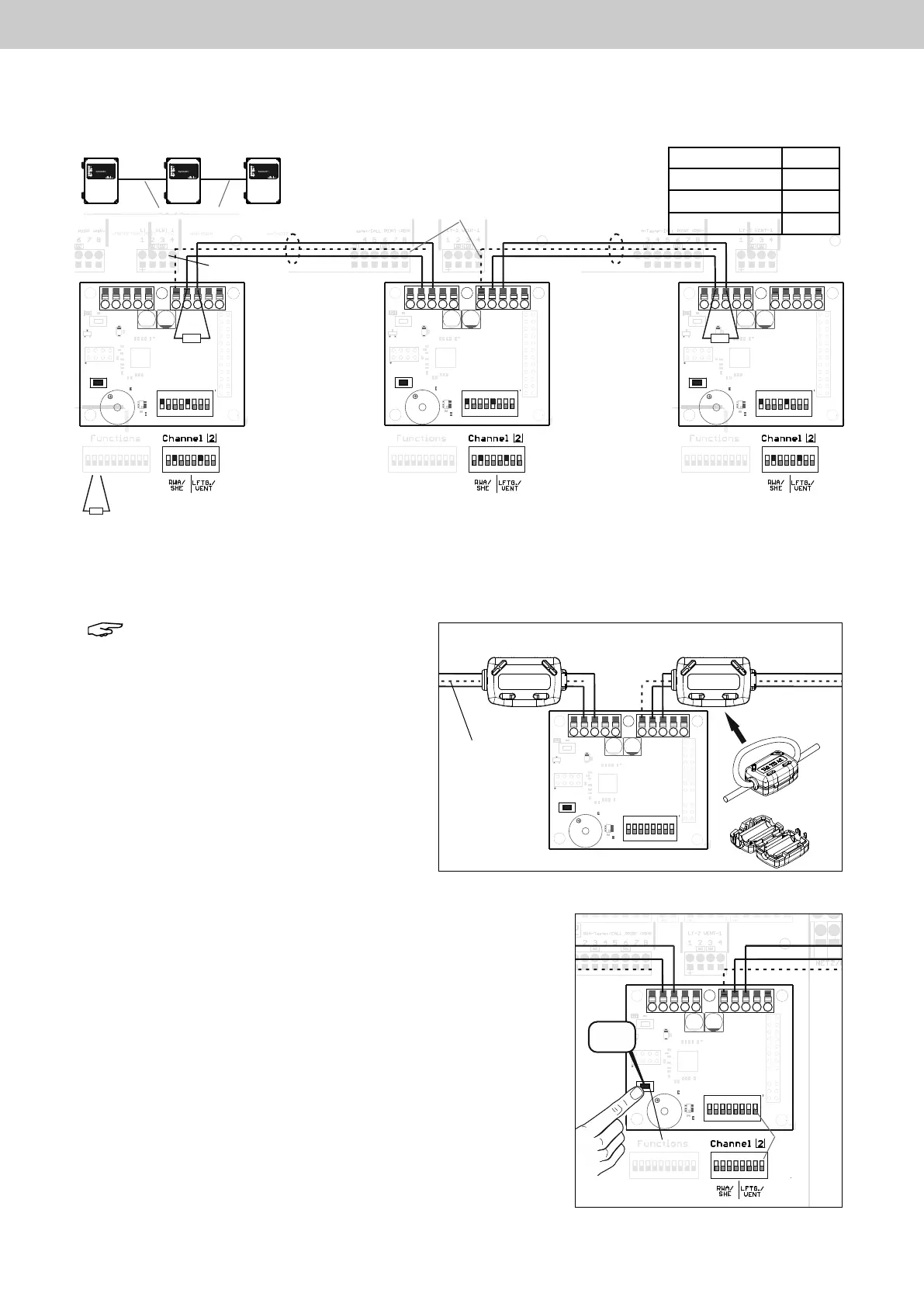
Note: Before commissioning, the enclosed
hinged ferrites must be sheathed at the
speciedpointsx at the 2-wire shielded
connection cable. The connecting cable
must be wound 2 x through the snap
ferrite (as a loop).
1 2 3 4 51 2 3 4 5
ON
12345678
ON
12345678
Sheathing point
Snap Ferrite
Sheathing point
Snap Ferrite
Sheathing point
for snap Ferrite
Snap Ferrite
2-wire shielded
connection
cable
Network board
EasyConnect
Connection-
line 2 x through
the snap ferrite