68
01/13424999386
10 Commissioning
Note: The information on commissioning
refers to the standard functions.
All DIP switches are in the OFF position
Note: Before commissioning, check that the batteries
aresecurelyxedbytheVelcrostrips.
Operation without adequately secured batteries is not
permitted!
After the electrical connection of all external components
(24 V drives, SHE manual call points, automatic detectors,
24 V ventilation push button, wind/rain sensors, etc.) and the
line monitoring modules:
► Connect the 230 V AC mains lead (L, N, PE) to the terminals
of the EasyConnect CP 20A (see page 14, point 8.1).
► Insert the battery fuse F3 (FKS 20 A).
► Check that all the fuses F2 - F5 are inserted
(see
pages 10 + 11).
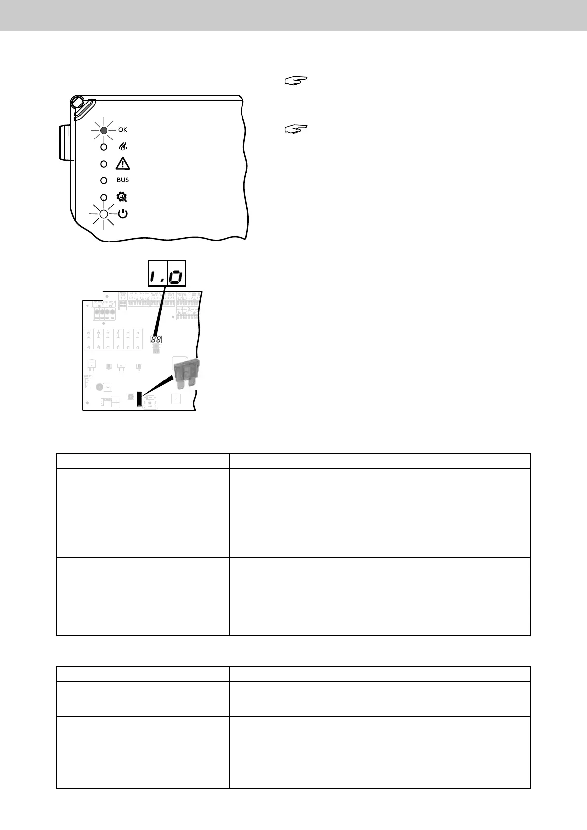
The 230 V mains supply door display lights up white, the door
display OK (ready for operation OK) lights up green.
The 2 x 7-segment display of the motherboard shows i.O. (OK).
The SHE control panel is ready for operation.
► Check that all the connected drives are completely CLOSED
(0 position). If not, be sure to CLOSE them using the con-
nected ventilation push button.
Door display ready for operation
OK (green)
Door display mains 230 V (white)
2 x 7-segment display
F3
Battery fuse F3
(yellow) FKS 20 A
Motherboard
TestofSHEmanualcallpoint
Actuation Eect
►BrieypressbuttonSHEactivation
(red) on the SHE manual call point
SHE trip: Display F A on the 7-segment display of the motherboard.
The red LED on the SHE manual call point and in the housing door of
the control panel lights up. The green LED (operation OK) on the SHE
manual call point and in the housing door of the control panel lights
up. The drive output is switched (green LED above the drive termi-
nals lights up). Drives move to completely OPEN. Signalling contact
2
(trip)closed.GreenLEDonventilationpushbutton(LTA25)ashes
fast (ventilation function barred).
►BrieypresstheReset/CLOSE
button (black) on the SHE manual call
point
Reset of the SHE trip.
Drives move to CLOSED (red LED above the drive terminals lights up).
The red LED on the SHE manual call point and in the housing door of
the control panel goes out. The green LED (operation OK) on the SHE
manual call point and in the housing door of the control panel lights
up. Signalling contact 2 (trip) open. After approx. 180 s, display I.O.
on the 7-segment display of the motherboard.
Test of ventilation push button
Actuation Effect
► Briey press button OPEN on the
ventilation push button.
The drive output is switched (green LED above the drive terminals lights
up). Drives move to OPEN. The display “Ventilation OPEN” (Type LTA
25 only) lights up.
► Briey press button CLOSE on the
ventilation push button.
The drive output is switched (red LED above the drive terminals lights up).
Drives move to CLOSED. The display “Ventilation OPEN” (Type LTA 25
only) does not light up.
During this run, press STOP. (for Type LTA 12 STOP = press both buttons
OPEN and CLOSE together). The drives stop.
Press ventilation button CLOSE again briey, the drives move to
CLOSED. The display “Ventilation OPEN” (Type LTA 25 only) is not lit.
EasyConnect+