TP-6803 1/15 25Section 1 Installation
1.10 ATS and Accessory
Connections
The following sections cover electrical connections of
the automatic transfer switches and RBUS accessories,
including the programmable interface module (PIM) and
the load control module (LCM) or load shed kit.
1.10.1 Transfer Switch Connection
Connect the ATS or remote start/stop switch. Connect
the load leads from the generator set to the Emergency
source lugs on the ATS. Route low-voltage
communication leads through separate conduit from the
AC power and load leads. All connections must comply
with applicable state and local codes.
Note: Do not use the Kohlerr Model RRT transfer
switch with the 14/20RESA or 14/20RESAL
generator set.
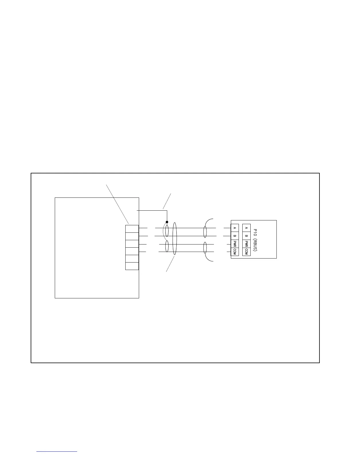
Communication connections for a Kohlerr
Model RXT transfer switch
One Model RXT transfer switch can be connected to the
generator set. See Figure 1-21. Use shielded,
twisted-pair communication cable to connect P10-1
through P10-4 on the transfer switch interface module to
the generator set terminal block connections A, B, PWR,
and COM. See Section 1.10.2 for the communication
cable recommendations and maximum cable length.
Note: Connections 3 and 4 on the generator set are not
used with the Model RXT transfer switch.
Engine start connection for other transfer
switches or a remote start/stop switch
Connect the engine start leads from the transfer switch
or remote start switch to terminals 3 and 4 on the
terminal block. See Figure 1-22. Route the engine start
leads through separate conduit from the AC power and
load leads.
1. Generator set terminal block. See Figure 2-4 for location. Check the decal on the generator set for terminal block connections.
2. Connect one end of each c able shield to GROUND at the generator set.
3. Communication cable Belden #9402 or equival ent 20 AWG shielded, twisted-pair cable. See Section 1.10.2, Cable Specifications.
4. Leave one end of each cable s hield disconnected. If accessory modules (PIM, LCM or load shed kit) are connected, see Section
1.10.3.
Interface Board on the
Model RXT Transfer Switch
Note: Generator set terminal block connections 3 and 4 are NOT USED with the Model RXT ATS.
Generator Set
B
A
RXT
COM
PWR
B
A
GND
A
B
COM
PWR
3
4
RBUS
12 VDC
3
1
2
4
4
COM
PWR
Figure 1-21 Model RXT Transfer Switch Communication Connection to Generator Set Terminal Block

 Loading...


