TP-6803 1/1526 Section 1 Installation
tp6803
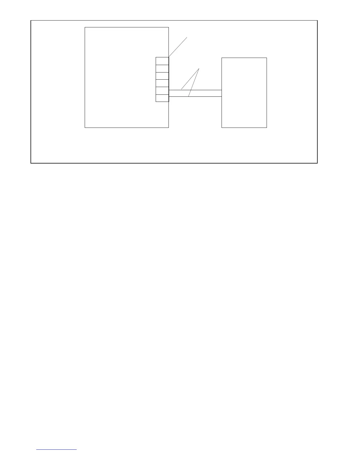
1. Generator Set Terminal Block. See the dimension drawings in Section 2 for location. Check the decal on the generator set for terminal
block connections.
2. Engine start leads 3 and 4. See the ATS manual for cable size specifications.
Generator Set
ATS
(with engine
start contacts)
A
B
COM
PWR
3
4
1
2
Figure 1-22 Engine Start Connections with Transfer Switch Models other than Model RXT
1.10.2 Communication Cab le
Specifications
RBUS Connections A and B
For the RBUS communication connections A and B to
the Model RXT transfer switch, optional PIM and/or
optional LCM or load shed kit, use 20 AWG shielded,
twisted-pair communication cable. Belden #9402
(two-pair) or Belden #8762 (single-pair) or equivalent
cable is recommended.
For outdoor installations, including those with buried
cables and/or conduit, use outdoor-rated Belden
#1075A or equivalent 20 AWG shielded, twisted-pair
communication cable.
PWR and COM Connections
For the PWR and COM connections, the cable size and
maximum cable length depends on the number of
modules connected. See Figure 1-23.
D For short cable runs shown in the first two rows of
Figure 1-23, use one pair in the two-pair
communication cable for the A and B connections,
and use the second pair for the PWR and COM
connections.
D For the longer cable runs shown in the last two rows of
Figure 1-23, use 12 or 14 AWG cable for PWR and
COM, and use the 20 AWG communication cable
specified above for the A and B connections only. In
this case, single-pair communication cable such as
Belden #8762 can be used for the A and B
connections.
1.10.3 System Co nnections with
Accessory Modules
See Figure 1-24 through Figure 1-28 for connection
options with accessory modules. Accessory modules
can include one Model RXT transfer switch, one
programmable interface module (PIM) and/or one load
control module (LCM) or load shed kit. Note the cable
shield connections shown in Figure 1-24.
The maximum cable length depends on the number of
optional modules connected. See Figure 1-23 for the
maximum cable lengths with 1, 2, or 3 modules per cable
run.

 Loading...


