TP-6803 1/15 27Section 1 Installation
Cable Size for PWR and COM Connections
Indoor or
Outdoor
Installation
Maximum length per run, meters (ft.)
Number of Modules per Run
1 Module 2 Modules 3 Modules
20 AWG Belden #9402 or equivalent, two-pair Indoor
61 (200) 31 (100) 21 (67)
20 AWG Belden #1075A or equivalent, two-pair Outdoor
61 (200) 31 (100) 21 (67)
14 AWG * —
152 (500) 152 (500) 122 (400)
12 AWG * —
152 (500) 152 (500) 152 (500)
* Use 12 or 14 AWG cable for PWR and COM connections only. For RBUS connections A and B, use s hielded, twisted pair c ommunication
cable specified in Section 1.10.2.
Figure 1-23 Total Cable Lengths for PWR and COM Connections
RXT
3
COM
PWR
B
A
4
PIM
LCM
or load
shed kit
Generator Set
COM
COM
PWR
COM
PWR
PWR
B
A
B
A
B
A
COM
PWR
B
A
COM
PWR
B
A
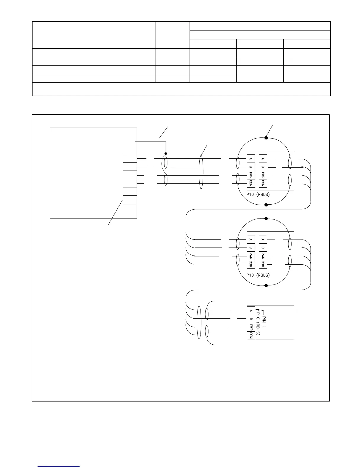
1. Generator set terminal block. See Figure 2-4 for location. Check the decal on the generator set for terminal block connections.
2. Connect one end of each c able shield to GROUND at the generator set.
3. Communication cable Belden #9402 or equivalent 20 AWG shielded, twisted-pair cable.
4. Connect shields together as shown.
5. Leave one end of each cable shield disconnected at the last device.
GND
Note: See Section 1.10.2, Cable Specifications.
A
B
COM
PWR
3
4
RBUS
12 VDC
1
2
5
5
Figure 1-24 Accessory Module Communication Connection Details

 Loading...


