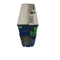
1.4.4 Digital servo amplifier concept
Operation and parameter setting
l
With our user-friendly software for setup through the serial interface of a PC
l
Direct operation by means of two keys on the servo amplifier and a 3-character LED display
for status display in case there is no PC available
l
Fully programmable via RS232 interface
Power section
l
Power supply: B6 rectifier bridge, directly off 3-phase earthed (grounded)
supply system, integral power input filter and inrush circuit
l
All shielding connections directly on the amplifier
l
Output stage: IGBT- module with isolated current measurement
l
Regen circuit: with dynamic distribution of the regen power between several
amplifiers on the same DC-link circuit. Internal regen resistor as
standard, external regen resistors if required
l
DC-link voltage 260 — 900 VDC, can be switched in parallel
Completely digital control
l
Digital current controller (space vector pulse-width modulation, 62.5 µs)
l
digital speed controller adaptable to most different load conditions (65µs or 250 µs)
l
Integral position controller with adaptation possibilities for customer needs (250 µs)
l Pulse direction interface integrated for connection of a servomotor to a stepping motor
control
l Evaluation of the resolver signals and sine-cosine signals of a high-resolution encoder
l Encoder simulation (incremental or SSI)
Auxiliary functions
l Adjustable setpoint ramps
l 2 analog monitor outputs
l
4 programmable digital inputs (normally, two are defined as limit-switch inputs)
l
2 programmable digital outputs
l
Freely programmable combinations of all digital signals
Integrated safety
l
Safe electrical separation to EN 50178 between the power input / motor connections and the
signal electronics, provided by appropriate insulation/creepage distances and complete electri
-
cal isolation
l
Soft-start, overvoltage recognition, short-circuit protection, phase-failure monitoring
l
Temperature monitoring of servo amplifier and motor
(when using our motors with our pre-assembled cables)
SERVOSTAR
®
601...620 Installation Manual 15
Kollmorgen 03/04 General

 Loading...