3.6.2 SSI encoder simulation - position output (X5)
The SSI interface (synchronous serial absolute-encoder simulation) is part of the delivered
package. Select the encoder function SSI (screen page “Encoder”). In the servo amplifier, the posi
-
tion of the motor shaft is calculated from the cyclically absolute signals from the resolver or encoder.
This information is used to create a position output in a format that is compatible with the standard
SSI-absolute-encoder format. 24 bits are transmitted.
SINGLE TURN selected: The upper 12 bits are fixed to ZERO, the lower 12 bits contain the posi
-
tion information. For 2-pole resolvers, the position value refers to the position within one turn of the
motor, for 4-pole resolvers it is within half a turn, and for 6-pole resolvers it is within a third of a turn.
Exception
: If an encoder with a commutation track is used as the feedback unit, then the upper 12
bits are set to 1 (data invalid!) until a homing run is performed.
MULTI TURN selected: The upper 12 bits contain the number of motor turns, the lower 12 bits con
-
tain the position information.
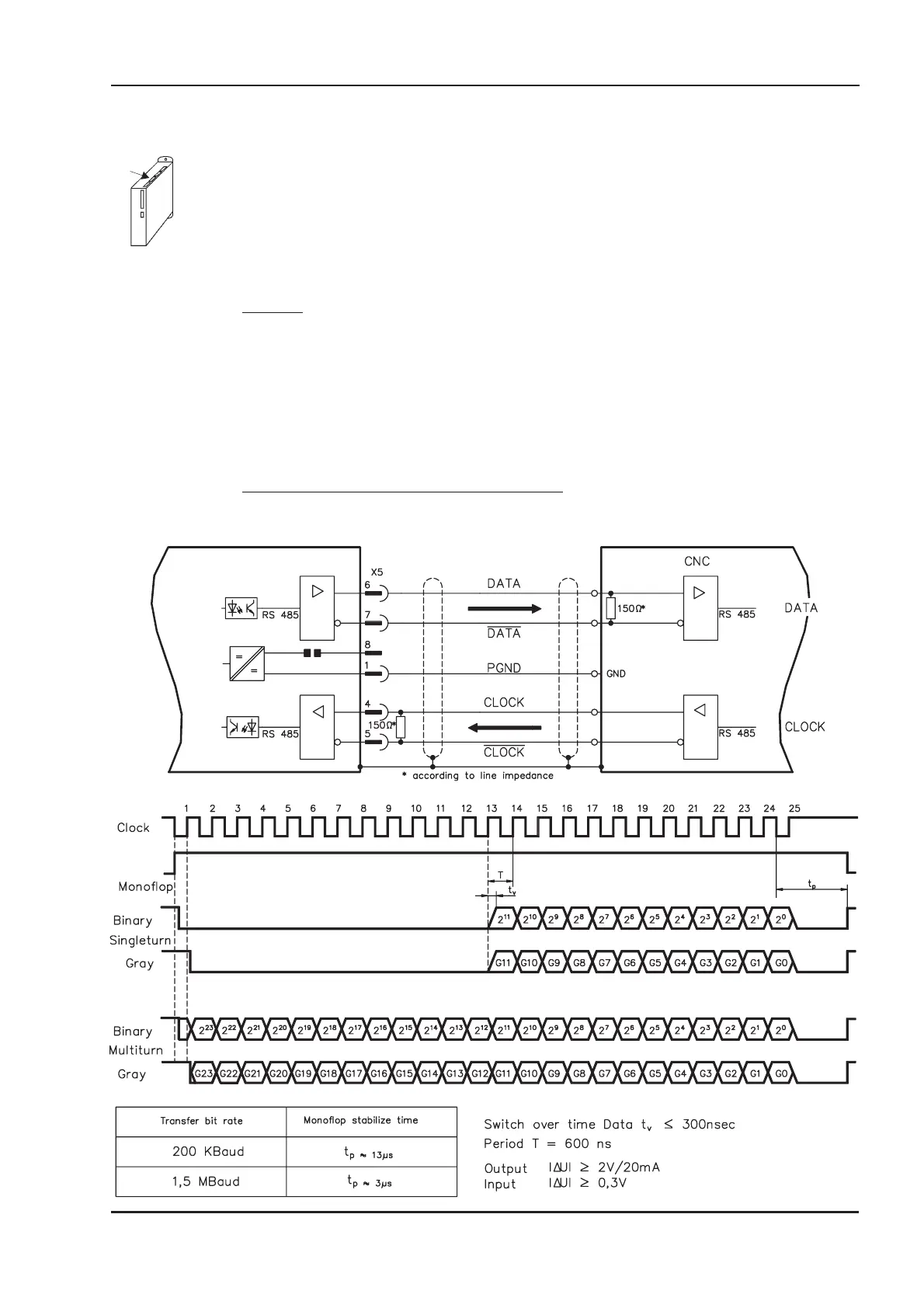
The signal sequence can be output in Gray code (standard) or in binary code (parameter
SSI-CODE). The servo amplifier can be adjusted to the clock frequency of your SSI-evaluation with
the SSI-TAKT parameter (200 kHz or 1.5MHz and inverted).
Drivers are supplied from internal supply voltage. PGND must always be connected.
Connection and signal description for SSI interface :
The count direction for the SSI interface is upwards when the motor shaft is rotating clockwise (loo
-
king at the shaft end).
SERVOSTAR
®
601...620 Installation Manual 47
Kollmorgen 03/04 Interfaces
SERVOSTAR 600

 Loading...