Home
Kollmorgen
Amplifier
SERVOSTAR 601
Kollmorgen SERVOSTAR 601
98 pages
Manual
To Next Page
To Next Page
To Previous Page
To Previous Page
Loading...
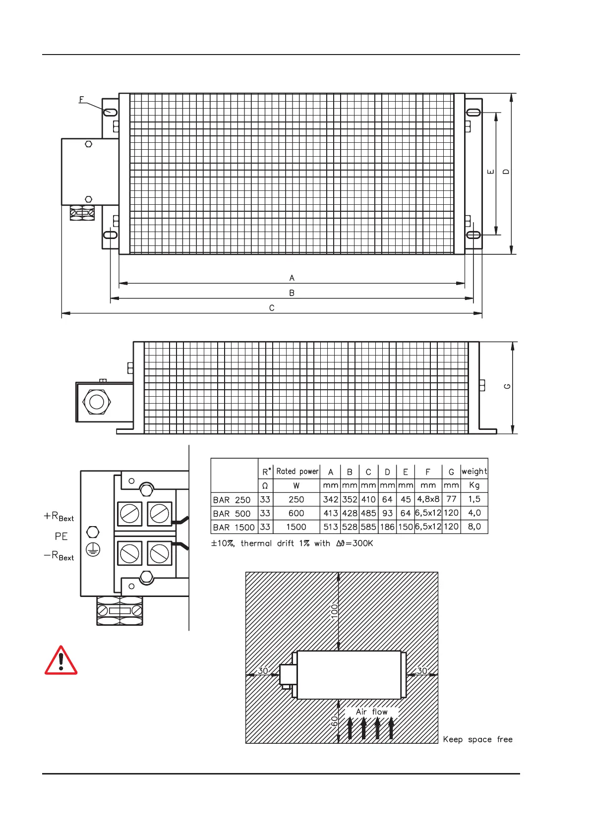
5.9.3
External
regen
resistor
BARxxx
Caution:
Surface
temperature
may
exceed
200°C.
Observe
the
requested
free
space.
Do
not
mount
to
combustible
surface
88
SERVO
STAR
®
601...620
Installation
Manual
Extensions
/
Accessories
03/04
Kollmorgen
87
89
Table of Contents
Main Page
Default Chapter
2
Edition
2
Table of Contents
3
Contents
3
Safety Instructions
6
European Directives and Standards
7
UL- Conformance
8
Abbreviations and Symbols
9
Symbols Used in this Manual
9
1 General
11
About this Manual
11
Prescribed Use (Use as Directed) of the Servo Amplifier
12
Nameplate
13
Instrument Description
13
Package Supplied
13
The Digital Servo Amplifiers of the Series SERVOSTAR 600
14
Operation Directly from Supply
14
Digital Servo Amplifier Concept
15
Connection to Different Mains Supply Networks
16
Components of a Servo System
17
Technical Data
18
External Fusing
18
Allowable Ambient Conditions, Ventilation, Mounting Position
19
Conductor Cross-Sections
19
Recommended Torque
19
LED Display
19
Grounding System
20
Control for Motor-Holding Brake
20
Regen Circuit
21
Switch-On and Switch-Off Behavior
22
Stop Function to en 60204 (VDE 0113)
22
Emergency Stop Strategies
23
2 Installation
25
Important Instructions
25
Assembly
26
Dimensions
27
Wiring
28
Connection Diagram
30
Example of Connections for Multi-Axis System
31
Pin Assignments
32
Notes on Connection Techniques
33
Shielding Connection to the Front Panel
33
Technical Data for Connecting Cables
34
Setup Software
35
General
35
Software Description
35
Use as Directed
35
Hardware Requirements
36
Operating Systems
36
Installation under WINDOWS 95 / 98 / 2000 / ME / NT / XP
36
3 Interfaces
37
Power Supply
38
Mains Supply Connection (X0)
38
Auxiliary Supply (X4)
38
DC-Link (X7)
38
Motor Connection with Brake (X9)
39
External Regen Resistor (X8)
39
Feedback
40
Resolver Connection (X2)
40
Encoder (X1)
41
Control Signals, Monitor Signals
42
Analog Inputs (X3)
42
Analog Outputs (X3)
43
Digital Control Inputs (X3)
44
Digital Control Outputs (X3)
45
Encoder Simulations
46
Incremental Encoder Simulation - a Quad B Position Output (X5)
46
SSI Encoder Simulation - Position Output (X5)
47
Interface for Master-Slave Operation, Encoder Input
48
Connection to a SERVOSTAR Master, 5V Signal Level (X5)
48
Connection to a Sine-Cosine Encoder (X1)
49
Connection to Encoders with 24V Signal Level (X3)
49
Interface for Stepper-Motor Controls (Pulse-Direction)
50
Connection to Stepper-Motor Controller with 5V Signal Level (X5)
51
Connection to Stepper-Motor Controller with 24V Signal Level (X3)
51
RS232 Interface, PC Connection (X6)
52
Canopen Interface (X6)
53
4 Setup
55
Important Notes
55
Parameter Setting
57
Multi-Axis Systems
57
Baud Rate for CAN-Bus
57
Node Address for CAN-Bus
57
Key Operation / LED Display
58
Key Operation
58
Status Display
58
Extended Menu Structure
59
Standard Menu Structure
59
Error Messages
60
Warning Messages
61
5 Extensions / Accessories
63
Option -AS-, Restart Lock for Personal Safety
63
Advantages of the -AS- Option
63
Functional Description
63
Block Diagram
64
Signal Diagram (Sequence)
64
Installation / Setup
65
Connection Diagram
65
Functional Test
65
Safety Instructions
65
Application Examples
66
Control Circuit
66
Moving Single Axes or Axis-Groups in Setting-Up Operation
66
Switching off Grouped Axes with Separate Working Areas
66
Mains Supply Circuit
67
Expansion Card -I/O-14/08
68
Fitting the Expansion Card
68
Technical Data
68
Light Emitting Diodes (Leds)
68
Position of the Connectors
69
Connector Assignments
70
Select Motion Task Number (Sample)
70
Connection Diagram
71
Expansion Card -PROFIBUS
72
Position of the Connectors
72
Fitting the Expansion Card
72
Connection Technology
73
Connection Diagram
73
Expansion Card -SERCOS
74
Position of the Connectors
74
Fitting the Expansion Card
74
Light Emitting Diodes (Leds)
75
Connection Technology
75
Connection Diagram
75
Expansion Card -Devicenet
76
Position of the Connectors
76
Fitting the Expansion Card
76
Connection Technology
77
Connection Diagram
77
Combined Module/Network Status LED
77
Expansion Card- ETHERNET
78
Fitting the Expansion Card
78
Connectors
78
Leds
78
Position of the Connectors
79
Connection Diagram
79
Expansion Card for Single Axis Controller -SAC
80
Fitting the Expansion Card
80
Technical Data
80
Position of the Connectors
81
Connector Assignments
81
RS-232 Communication X17 (Subd 9-Pin, Plug)
81
Devicenet Communication X16 (Phönix, 5-Pin)
82
RS-485 Communication X17 (Subd 9-Pin, Plug)
82
Digital Inputs/Outputs, Connector X18 (Subd 26-Pin, Socket)
83
Expansion Module -2CAN
84
Position of the Connectors
84
Fitting the Expansion Module
84
Connection Technology
85
Connector Assignments
85
Connection Diagram
85
Accessories
86
External 24V DC / 5A Supply
86
External 24V DC / 20A Supply
87
External Regen Resistor Barxxx
88
External Regen Resistor BAR(U)XXX
89
Motor Choke Box 3YL-20
90
6 Appendix
91
Transport, Storage, Maintenance, Disposal
91
Removing Faults/Warnings
92
Glossary
94
Order Numbers
96
Index
97
North America
98
Other manuals for Kollmorgen SERVOSTAR 601
Instruction Manual
122 pages
Related product manuals
Kollmorgen SERVOSTAR 640
118 pages
Kollmorgen SERVOSTAR 614
122 pages
Kollmorgen SERVOSTAR 300
138 pages
Kollmorgen SERVOSTAR 400
88 pages
Kollmorgen S700
166 pages
Kollmorgen S300
138 pages
Kollmorgen S7240
166 pages
Kollmorgen S70101
138 pages