EasyManuals Logo

Kollmorgen SERVOSTAR 601 Assembly And Installation Guide

Kollmorgen SERVOSTAR 601
98 pages
To Next Page IconTo Next Page
To Previous Page IconTo Previous Page
Page #85 background imageLoading...
Page #85 background image
5.8.3 Connection technology
Standard shielded cables can be used for the RS232 and CAN interfaces.
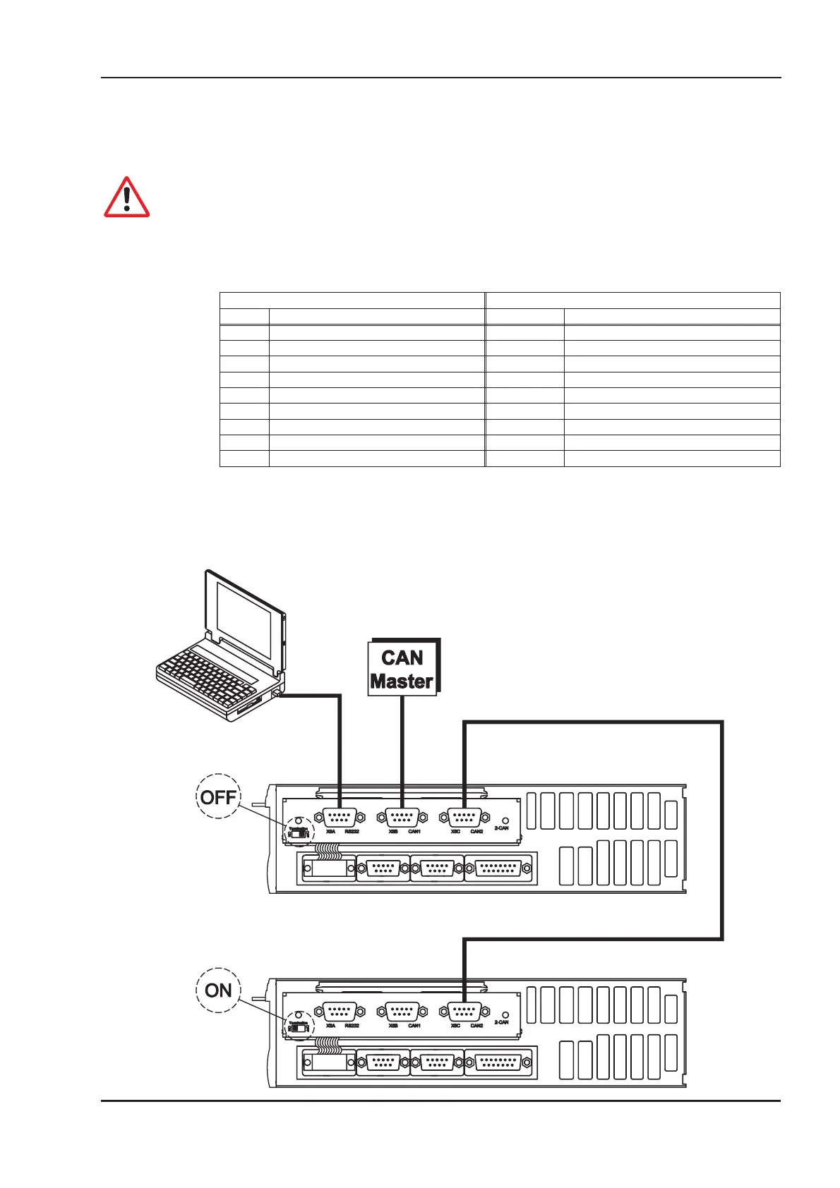
If the servo amplifier is the last device on the CAN bus, then the switch for the bus ter
-
mination must be set to ON.
Otherwise, the switch must be set to OFF (condition as delivered).
5.8.4 Connector assignments
RS232 CAN1=CAN2
X6A Pin Signal X6B=X6C Pin Signal
1 Vcc 1
2 RxD 2 CAN-Low
3 TxD 3 CAN-GND
44
5 GND 5
66
7 7 CAN-High
88
99
5.8.5 Connection diagram
SERVOSTAR
®
601...620 Installation Manual 85
Kollmorgen 03/04 Extensions / Accessories

Table of Contents

Other manuals for Kollmorgen SERVOSTAR 601

Questions and Answers:

Question and Answer IconNeed help?

Do you have a question about the Kollmorgen SERVOSTAR 601 and is the answer not in the manual?

Kollmorgen SERVOSTAR 601 Specifications

General IconGeneral
BrandKollmorgen
ModelSERVOSTAR 601
CategoryAmplifier
LanguageEnglish

Related product manuals