2J0/2J1/2J2-4
2-2-3
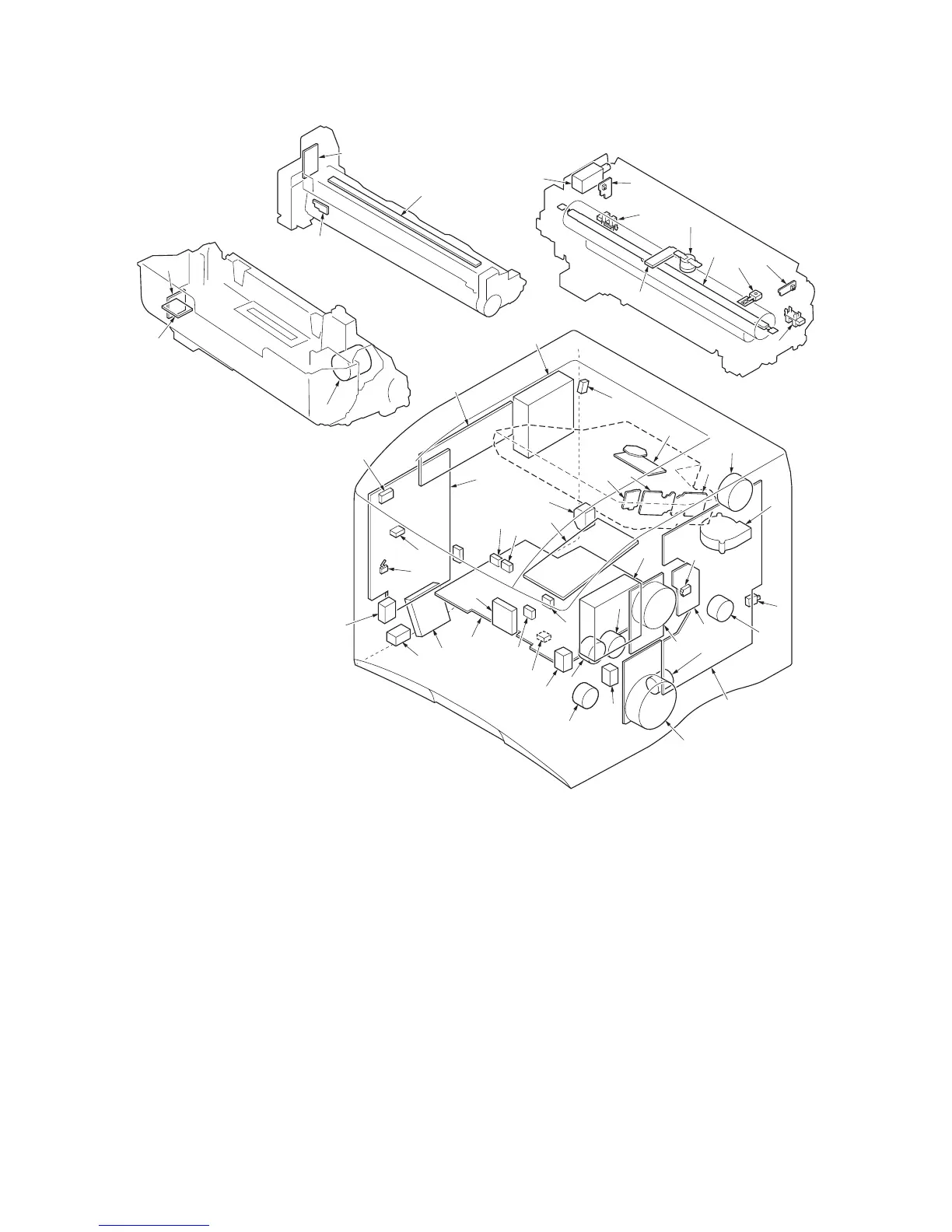
Figure 2-2-3Electrical parts layout (45/47 ppm printer [EUR/USA model])
1. Main PWB .................................................... Controls the software such as the print data processing and provides the
interface with computers.
2. Engine PWB................................................. Controls printer hardware such as high voltage/bias output control, paper
conveying system control, and fuser temperature control, etc.
3. Operation panel PWB .................................. Indicates the LCD message display and LED indicators. Controls key
inputs.
4. Connect-R PWB........................................... Interconnects the engine PWB and the electrical parts.
5. Connect-L PWB ........................................... Interconnects the engine PWB and the electrical parts.
6. Drum PWB ................................................... Relays wirings from electrical components on the drum unit. Drum indi-
vidual information in EEPROM storage.
7. Developer PWB ........................................... Relays wirings from electrical components on the developing unit.
8. APC PWB 1 ................................................. Generates and controls the laser beam.
9. APC PWB 2*
1
.............................................. Generates and controls the laser beam.
10. PD PWB....................................................... Controls horizontal synchronizing timing of laser beam.
11. Eraser lamp PWB ........................................ Eliminates the residual electrostatic charge on the drum.
12. Waste toner sensor PWB............................. Detects the waste toner box being full.
Developing unit
Drum unit
Fuser unit
45/47 ppm printer
(EUR/USA model)

 Loading...