2J0/2J1/2J2
1-5-33
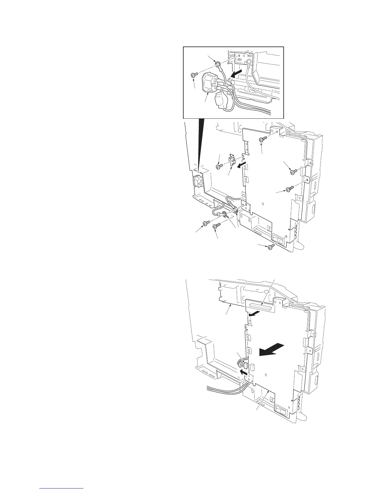
7. Remove seven screws-A and drum ground-
ing plate and two grounding terminals.
8. Remove one screw-B and grounding termi-
nal.
9. Remove the AC inlet.
Figure 1-5-44
10. Remove one connector.
11. Remove the PWB connector between con-
nect-L PWB and power source unit.
12. Remove the power source unit.
Figure 1-5-45
Screw-B
AC inlet
Screw-A
Screw-A
Screw-A
Screw-A
(M3)
Screw-A
(M3)
Screw-A
(M3)
Screw-A
Drum
grounding
plate
Grounding
terminal
Grounding
terminal
PWB connector
Connect-L PWB
Connector
Power source unit
 Loading...