Page 12 / 89 Section 2. Controls and connections
2.3. Electrical connections
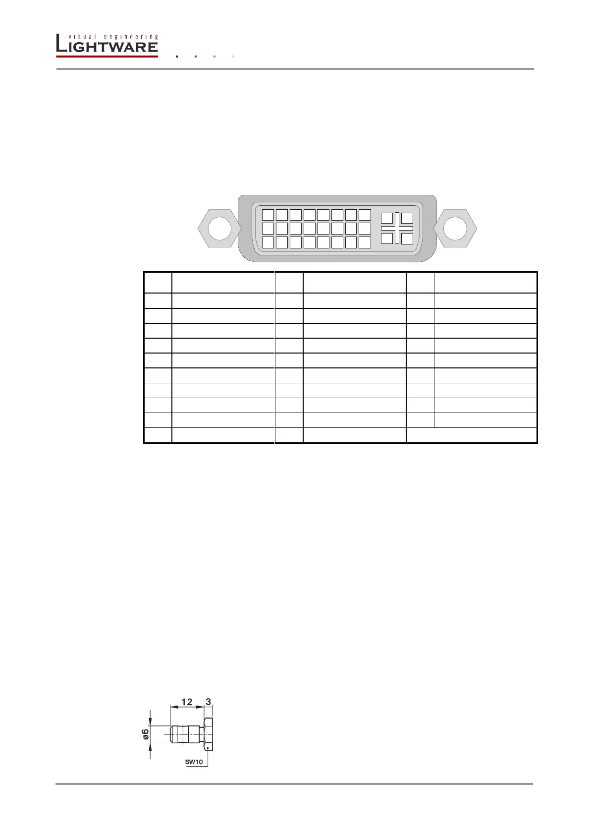
2.3.1. DVI inputs
Standalone DVI-Plus matrices provide 29 pole DVI-I connectors for inputs, however only
digital pins are internally connected. This way, users can plug in any DVI connector, but
keep in mind that analog signals (such as VGA or RGBHV) are NOT processed. Fix +12 dB
cable equalization is provided, this way DVI cables up to 20 meters can be used on all
inputs. Always use high quality DVI cable for connecting sources and displays.
Table 2-1. DVI-I digital only connector Single Link pin assignments
2.3.2. DVI outputs
Standalone DVI-Plus matrices provide 29 pole DVI-I connectors for outputs, however only
digital pins are internally connected. This way, users can plug in any DVI connector, but
keep in mind that analog signals (such as VGA or RGBHV) are NOT processed. Thanks to
the fix +6 dB pre-emphasizing circuit, DVI cables up to 15 meters can be used. For using
longer cable runs at outputs, use fiber optical DVI transmitters (like Lightware DVI-OPT-
TX110) or active DVI repeaters/extenders. No output reclocking is provided.
Fiber Cable powering
As a special feature standalone DVI-Plus matrices are able to supply 500 mA current on
DDC +5V output (pin 14 on output connectors) to power fiber optical DVI cables. Standard
DVI outputs or graphic cards supply only 55 mA current on +5V output, thus unable to
power directly a fiber optical cable.
Info: The matrix switcher does not check if the connected sink supports Hotplug or EDID signals
but outputs the selected signal immediately after switch command.
2.3.3. Equipotential connector
The purpose of additional potential equalization is to equalize potentials
between different metal parts that can be touched simultaneously, or to
reduce differences of potential which can occur during operation
between the bodies of medical electrical devices and conductive parts
of other objects. Ø6 mm plug made of nickel-plated brass can be found
on the left side of the unit’s back for potential equalization.