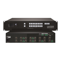
Standalone MX DVI-Plus family
User’s Manual
Section 6. Web control – Using built-in website Page 43 / 89
6.1. Control menu
6.1.1. Crosspoint switching
Figure 6-2. Built-in website crosspoint array
This menu contains the crosspoint area and the preset area. After connecting to a new
device, this menu appears by default. 1; 2; 3… columns represent the inputs, and the 1; 2;
3… rows represent the outputs. Each green square represents a live connection. Click on
the desired grey square to make the connection. When the mouse pointer hovers over the
array, the corresponding input and output numbers are highlighted in red to help switching.
6.1.2. Mute outputs
Outputs can be easily muted by clicking the button titled 'M' beside the output. This means
that no signal will be present at this output. If muting is active the background turns to black.
6.1.3. Lock outputs
Outputs can be locked to any inputs. After locking an input to an output no switching is per-
mitted for that output unless it is unlocked again. If lock is active, background turns to red.
Info: Loading a preset doesn't change neither the lock state nor the switch state of a locked
output. If an output is locked to an input before preset loading, it will also be locked that
input after preset loading, so locked outputs ignore the preset.
6.1.4. Preset operations
Preset operations can be done in the right panel of the Control Set and View
Crosspoints page. Lightware matrices have 32 preset memories which can be loaded and
saved any time.
Info: A preset setting stores a full configuration of all outputs, so preset loading have an effect
on every output, except the locked ones.
Save Preset
Step 1. Make the desired configuration on matrix switching area.
Step 2. Select the desired preset memory location.
Step 3. Press the Save Preset button. A message box confirms that the preset is stored.
Load Preset
Step 1. Select the preset memory location (Preset1...Preset32) you want to load as next
configuration.
Step 2. Press the Load Preset button. Now the preset is loaded
Step 3. The new I/O configuration is displayed on the matrix switching area.