215585 126 Revision A
$
%
&
'
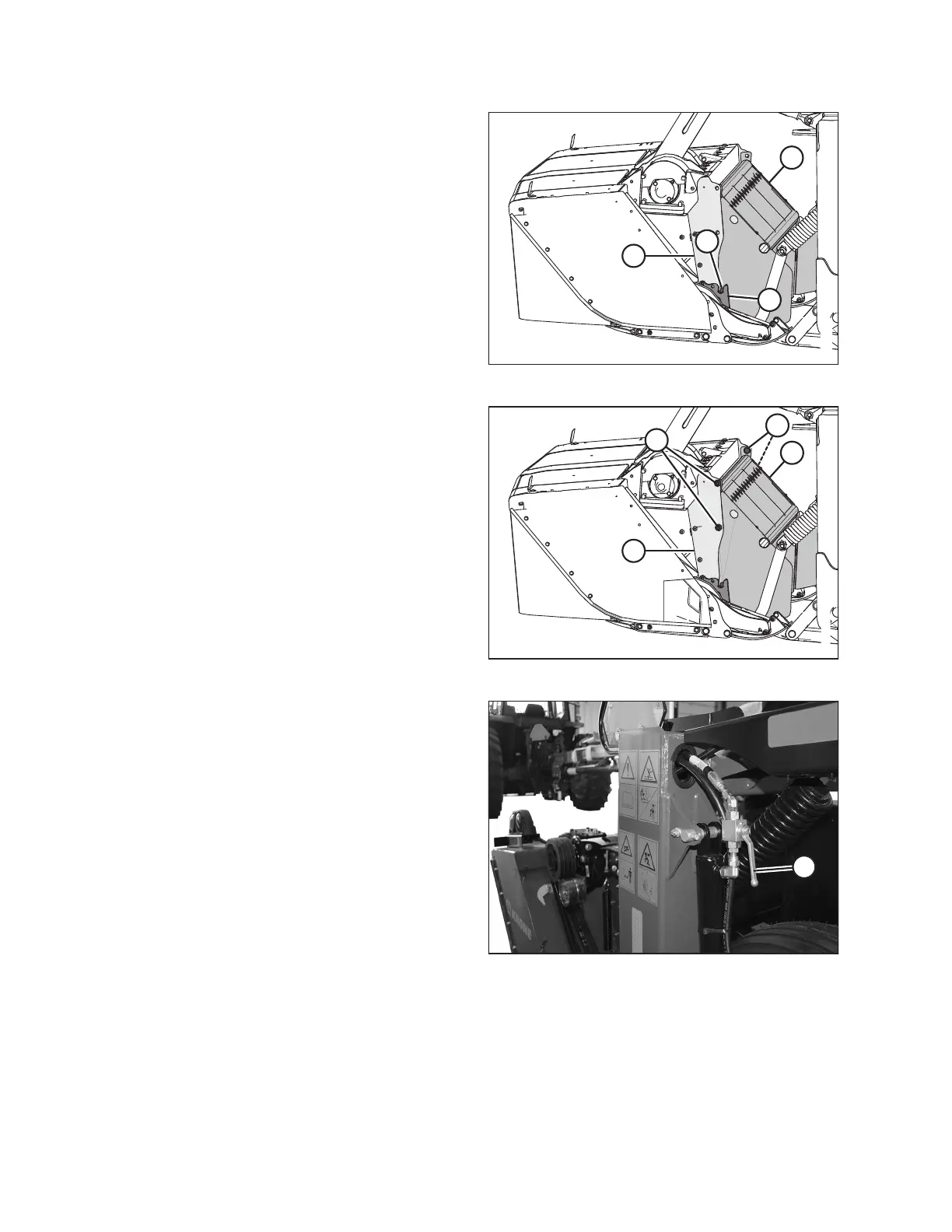
Figure 6.42: Left Side of Header – Right Opposite
4. Position shield (A) so that pins (B) (one on each side)
engage the slots in cutterbar support (C) and the bolt holes
align with panel (D).
$
%
&
$
Figure 6.43: Left Side of Header – Right Opposite
5. Install four M16 hex head bolts (A), nuts, and flat washers
to secure shield (B) to panel (C). Ensure the bolt heads face
inboard.
$
Figure 6.44: Lift Cylinder Lock-Out Valves – Open
Position
6. Open lift cylinder lock-out valves (A) on both sides of the
rotary disc pull-type. Valve handles should be in the open
position (in line with the hose).
COMPLETING ROTARY DISC PULL-TYPE ASSEMBLY