215585 12 Revision A
3.2 Attaching Hitch to Carrier Frame
The connection point on the carrier frame secures the hitch to the frame and allows the pull-type to pivot.
$
Figure 3.9: Carrier Frame
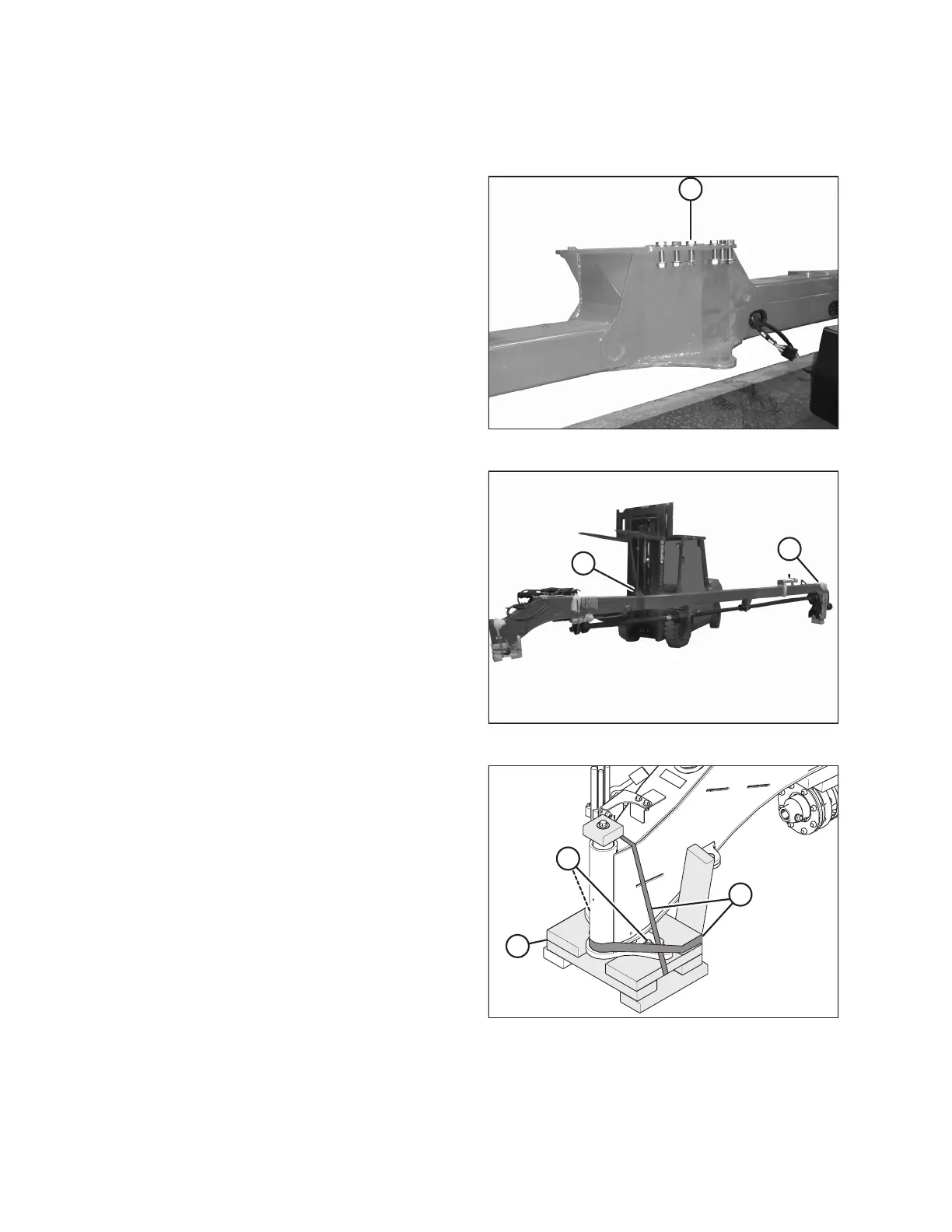
1. Remove six M20 bolts (A), washers, and nuts from carrier
frame at the hitch attachment location. Retain bolts,
washers, and nuts.
$
%
Figure 3.10: Lifting Hitch
2. Place sling (A) around the hitch frame. Adjust sling position
until hitch is balanced when lifting.
• R113 PT: Approximately 2.7 m (106 in.) from the edge
of tractor end (B) of the hitch
• R116 PT: Approximately 3.5 m (138 in.) from the edge
of tractor end (B) of the hitch
3. Raise the hitch approximately 610 mm (24 in.) off
the ground.
$
%
&
Figure 3.11: Hitch Packing
4. Cut banding (A) securing wood supports, then
remove supports (B).
5. Remove two bolts (C) securing wood support to hitch pin.
Discard bolts.
ASSEMBLING THE ROTARY DISC PULL-TYPE – WITH OR WITHOUT THE DEALER-INSTALLED TRANSPORT