215585 11 Revision A
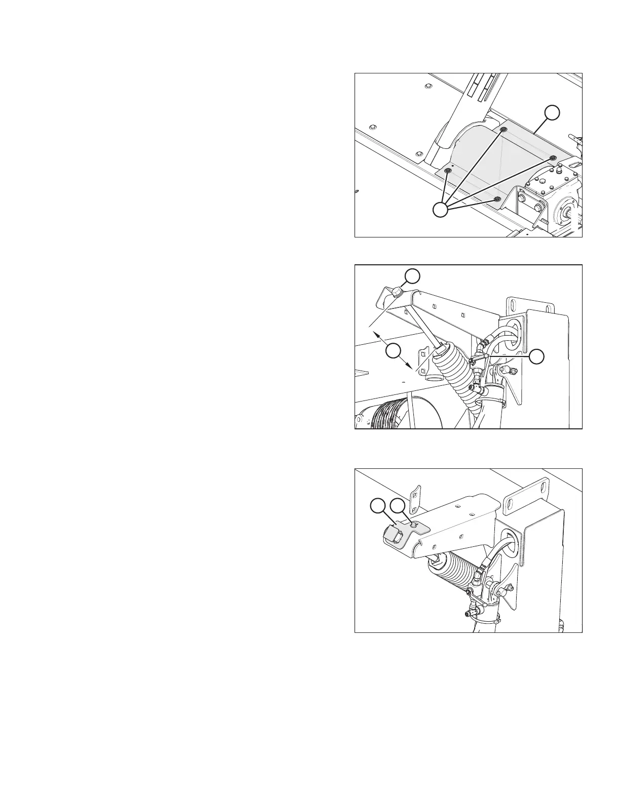
Figure 3.6: Top Shield – Left of Center-Link
8. Install top shield (B) and secure with four M10 hex head
bolts (A) and flat washers. Torque to 28.5 Nm (21 lbf·ft).
NOTE:
If transport is also being installed, leave bolts (A) loose.
These bolts will be tightened when installing the lighting
harness.
Figure 3.7: Lift Cylinder Lock-Out Valve and
Adjuster Bolt
9. Close lock-out valve (A) on each rotary disc pull-type lift
cylinder by turning the handle to the horizontal position.
Repeat on opposite side.
10. Turn adjuster bolt (B) to set dimension (C) to 130 mm
(5 1/8 in.). Repeat on opposite side.
• Turn bolt clockwise (towards spring) to increase float
• Turn bolt counterclockwise (away from spring) to
decrease float
Figure 3.8: Adjuster Bolt Cover Plate
11. Reposition cover plate (A) over float spring adjuster bolt as
shown. Secure cover plate (A) by tightening bolt (B). Repeat
on opposite side.
ASSEMBLING THE ROTARY DISC PULL-TYPE – WITH OR WITHOUT THE DEALER-INSTALLED TRANSPORT