215585 64 Revision A
$
%
&
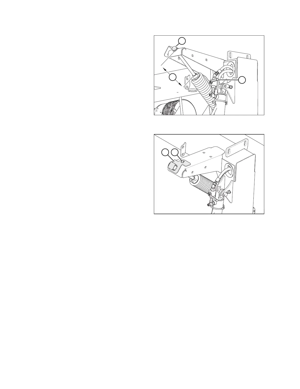
Figure 4.9: Lift Cylinder Lock-Out Valve and
Adjuster Bolt
11. Close lock-out valve (A) on each rotary disc pull-type lift
cylinder by turning the handle to the horizontal position.
Repeat on opposite side.
12. Turn adjuster bolt (B) to set dimension (C) to 130 mm
(5 1/8 in.). Repeat on opposite side.
• Turn bolt clockwise (towards spring) to increase float
• Turn bolt counterclockwise (away from spring) to
decrease float
$ %
Figure 4.10: Adjuster Bolt Cover Plate
13. Reposition cover plate (A) over float spring adjuster bolt as
shown. Secure cover plate (A) by tightening bolt (B). Repeat
on opposite side.
ASSEMBLING THE ROTARY DISC PULL-TYPE – FACTORY-INSTALLED TRANSPORT